ZBrushCentral

ZBrush for CNC Carving

I’ve seen a couple of threads on this site that address the issues of CNC carving, but I always wonder exactly which type of ZBrush file is being recommended as a first step.

In ZBrush, I think that you have basically 2 types of files to work with. The main files are ZBR files, which consist of pixols.

Then you have models, which are basically 3d tools that you build and then can save as ZTL files. These consist of a mesh. Am I on track here?

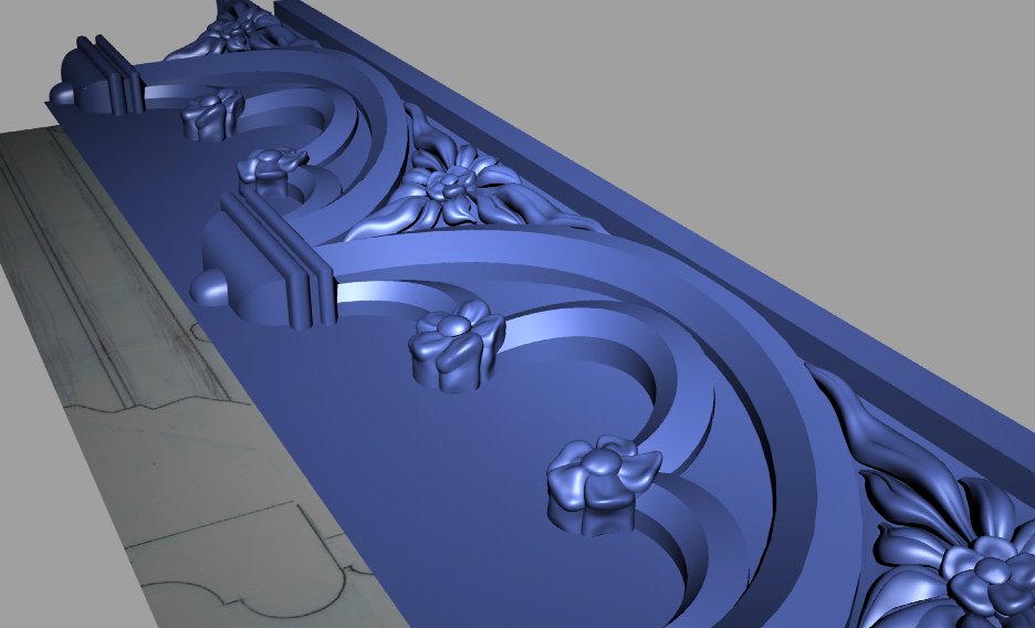
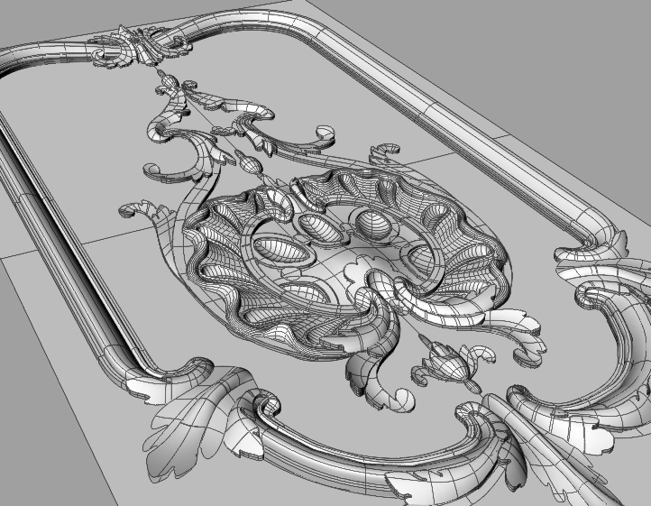
The models or tools can be snapshot onto the workspace, where they are then static, but can be saved as a ZBR file. Here is my main question. Is the ZBR file a useful first step for someone who wants to use a CNC router to create a base relief carving from wood or foam?

The answer may depend on whether or not the ZBR file can be converted into something that the CAM software can read. I think that Millwizard, for example, can read STL files. Can the ZBR file be converted into an STL? I mean, the ZBR pixols have x,y,and z data, right? Isn’t that enough data for a converter to create an STL? If so, is such a converter available?

I think that if you were creating a bas-relief carving in a CNC machine, the ZBR file would be really nice as a starting point, because you can build up a complex sculptural scene with snapshots of the ZTL’s that you have available, with everything including a background that can be carved. Or, are people doing this by creating the whole carving as a ZTL and converting that to an STL for the CAM software?

I hope that this question makes sense. Thanks.

Steve

there are several members that use rapid prototyping to bring their models from zbrush into the real world. I think bill robertson does…that’s just off the top of my head…but there are several others like I said…build it in z and then export it to others programs to convert the formats I believe…never done it myself but want to at some point…good luck and others should hopefully respond better on this subject.
ron
[email protected]

at work we use a cnc hardware and we also produce models from zbrush.
usually we export obj files, and our software can read directly that.

obj or dxf is very common format that usually a software can read. remember that hardware can be limited then you can’t repdroce all fine dectails, especially skin pores or similar, if you use start remotion system, if you use 3d printer or other you can have nice result.
zbl is not a format readable from otehr software than zbrush (from that i know) you need to convert it.
have a nice day.

You can create a tool and export the tool as OBJ… I use Rhino but there are several other packages that can open an OBJ and save as STL. Some CAM programs can read in a significant amount of poly data and others cant. Visual Mill, Desk Proto and MasterCAM have worked for me.

Good luck.

IC

stl files don’t have any drive faces( a face,line,arc,point etc of which the cam can machine), in mastercam the stl object( lines) need to be converted to a nurbs object before you can surface machine it.
As a test i used amapi to convert the zbrush obj file to an stl file which then needed to be converted to a nurbs object in order to simulate machining.

If you’re modelling for prototyping, you will create 3d tools in zbrush. You can save these tools as ztl files while you’re editing them in zbrush, but when you’re done you will need to export them to obj or dxf. I have never had luck with dxf personally.

As others have mentioned, some software can work directly with the .obj, and a lot of others need it converted to .stl. I use rhino like routb. I also find rhino very helpful for setting up the stuff I want to cut because it works very nicely with real world units. Other packages may do that well also.

A lot of the advice around 3d modeling is oriented towards people modelling for animation. Especially when they’re talking about topology, quads, edge loops etc… My (limited) experience with modelling for prototyping is that if you can express your form in few enough polygons for your software that drives your cutting machine then you don’t have to worry about it a bit. If not then some understanding of topology can help you drastically cut down on the number of polygons that you need and get the job done. This number is much higher than what you can get away with in animation, but much lower than a hyperdetailed zbrush sculpt AFAIK.

Good luck, and please check out my website (http://www.wargminis.com). I just updated it on the first of the year.

OK… that is misleading. Mastercam (at least since V8) has been able to directly machine STL files… It may not be able to display high poly counts but it can machine them… STL files are poly surfaces… Triangles with faces…

I think what ullach is trying to say is that he thinks that you cant drive a tool path on a poly surface the way you can on a NURBS… Nurbs surfaces have U and V that provide directional info to Mastercam while generating tool paths that follow a surface. A triangulated mesh on a whole does not have a U and V… However, most CAM programs (including mastercam) have functions to drive the tool path direction using curves. Use the direction of the curves in conjunction with the surface normal of the mesh… Walla, no need to convert to NURBS…

IC

Ulach,

When you go to select a drive or check surface select to use a CAD file for the drive. Change the file of type to STL. Most likely you wont even see the STL but it will make a tool path when you calculate.

IC

If you don’t mind, madrenderman, routb & ullach, what are you making with prototyping? Any pictures? Are you running the machines yourself, if so what kind of machine?

I know there are a couple more people who RP their work on the board, or at least have others do it. Billb (?) and Steevo are two that come to mind. There is other person that contacted me about it awhile ago, but I forgot who that was.

Hey Guys,

Check out these sites for CNC work done from polygon data (as opposed to Nurb data)
BNT studios
Mecsoft article
BNT4CNC

The thing that Bill (of BNT Studio) is doing with ZBrush is using the Alpha’s
in a way that gets him Z depth (CNC Z depth, not Zbrush).
Anyway he checks in here once in while, I think as Billb as billrobertson42 said before.

Yes, that’s him. He does really amazing stuff. He’s also a really nice and helpful guy.

Thanks very much to all who have contributed to this thread.

IC, it was your post on another board that started me looking at ZBrush for CAM. I had seen a demo video of Artcam in action and was impressed by it’s capabilities, but it is pricey. ZBrush has got very much of the same type of modeling capabilities, or maybe more so. It’s not an integrated CAM solution, of course, like Artcam seems to be. But, there may be advantages to separating the design function from the CAM function.

Bill, I don’t think that I’ll be doing prototyping. I’m interested in making decorative and functional objects, and maybe some wacky themed signs and interior design elements. So, some things will be the 3D sort of thing that you can walk all the way around and look at all sides and some will be 2.5D and will look like things jutting out from a background, as a bas relief. I can get a mental handle on the Z tools exported as OBJ’s for the 3D side of things, but the bas relief stuff where the individual elements are all combined together on a background, is that is where the other programs like Rhino will come into play. Would you take multiple OBJ’s into Rhino and arrange them so they are partially coming out of the face of a block and once you get that composition right, export it as an STL? Maybe I’m looking at this the wrong way. Any thoughts?

Also Bill , congrats on the site upgrade. I’d seen it before, and it looks really good now.

Ullach, thanks for getting the discussion going on nurbs and stl’s. If you decide to experiment with the suggestions of some of the others, I’d love to hear about your results.

Bpmufx, I appreciate those links.

I agree with Bill, I’d love to see the work of others in rapid prototyping, but I’d REALLY love to see pictures of work by anybody who is making final products, whether it’s signs, architectural details, molds for casting art pieces, etc.

Thanks again guys for a really helpful discussion.

Steve

Take a good look through BNT4CNC site (previous post).
I know he’s got pics of matched molds machined from his model data.
He’s also done some matched shelled components.

Please elaborate on what you goal is. I can’t tell if you’re looking for:

1-mold design
2-surface machining
3-Bas-relief routing

But anyway, to directly answer a few of your questions:

I’ve seen a couple of threads on this site that address the issues of CNC carving, but I always wonder exactly which type of ZBrush file is being recommended as a first step.

Answer:
The Pixol is not a 3d body therefore not suitable for Postwork not to mention the fact that no CAM App reads native .ZTL files.
OBJ is really the only best choice from ZBrush, however as others have said, you may not be done there and thats where is becomes very difficult to advise without knowing you CAM software and it’s cababilities.

Here is my main question. Is the ZBR file a useful first step for someone who wants to use a CNC router to create a base relief carving from wood or foam?

Answer:
No, as stated above .ZTL is not a readable file for any CAM app that I’m aware of.
But what can be done is to tweak a 2d image, convert to an alpha, create an alpha skin, export as OBJ. Then you’re back to having a useful file type.

Can the ZBR file be converted into an STL? I mean, the ZBR pixols have x,y,and z data, right? Isn’t that enough data for a converter to create an STL? If so, is such a converter available?

Answer:
You’ll need a another app to do that convertion. Rhino is a great convertion tool.

Hope this helps.

Hi guys,

Here are couple of shots of things I have done using Maya, Rhino, Zbrush and Visual Mill or MasterCam… Why so many programs… Well, Maya is good at Poly modeling, SUBDs and NURBS… Good Starting point… I take my surface and go out to Rhino… (If not already poly, it is converted in Maya before export as OBJ). I use Rhino to position and scale the poly object. I export only parts of the surface that need organic sculpture (OBJ) . Sculpt up in ZB and export out as OBJ and re-import and merge with the original unsculpted file in Rhino… (Be patient… Rhino is a trooper and it will import the OBJ even if its 250MG… Can take 1/2 hr or more…) Sort through the file to select only surfaces that will see the light of day… (CAM programs can be touchy with the amount of polys you try to import. Dont export anything that will never influence a tool.) Export to STL and import into your favorite CAM…

For a larger carving using a 1/8" ball end… Polys on organic surfaces should be no larger than 0.05" or so…

For small mini mill parts using tapered bits with .005 flat tips. Polys should be no larger than .001…

The flowers and leafs are Z brushed…
sculotd_Frnch_arch1.jpg

Attachments

SS_wire.jpg

Here is the finished part after ZB and CAM… (real Photo)
carving_sm2.jpg

How big is piece that routb?

@routb: I see ‘undercuts’ in the design, but not in the final result. You have to carve that manually right? Or is the cam so clever that it can tilt the router head and ‘undercut’?
Lemo

I checked out the stl options, and you can machine the stl file by setting ALL LINES option on mastercam in the machine surface tool path and also agree with, only to import what you want to cut. I imported the headtopology file from zmapper examples and successfully machined a face mask mold.

like your work.

No undercuts on these… The picture of the arch moulding is only a surface. It was machined by one of my clients and I have never seen the final result. Your right though… The base of the flowers would represent an undercut but those surfaces were never sent to CAM… Just quick extrusions off of the base of the pedals to show the thickness to the client. In the end, the pedals act as blocking surface to the arch below and the base even further below. I rolled all of the edges of the pedals to creat a gracefull fall off which Im sure can be seen in the final.

There are 5 axis machines that could handle such undercuts but I have little experience with those.

There are plenty of methods for cutting multi sided objects. I could, for instance, cut a 10 ft replica of the statue of liberty using only a 3 axis CNC router. Its a matter of finding ways to break the surface up into puzzle pieces, orienting each piece for machining and putting the puzzle back together in the end… They do it all the time in large scale foam cutting… Cut the basic shapes using a CNC hot wire cutter and then cut the detail using ultra long ball end mills… Ill try to find the name of the place that does it…
I saw a 15 ft replica of Shrek Hard coated and painted… Looked awsome.

Thanks,

IC

IC

Hey Ullach - can you clarify exactly the proceedure to your last post re STL options?

I’m using MC R-8 and I don’t find anything like you referring to. Please note which release you’re using also.
Thanks