ZBrushCentral

Topology is broken after reconstruct subdivs.

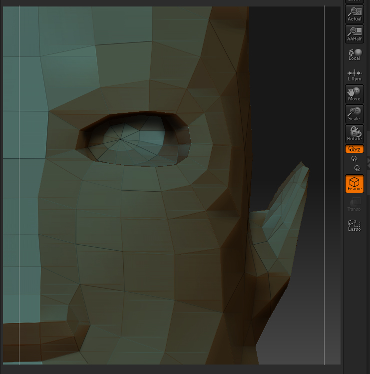
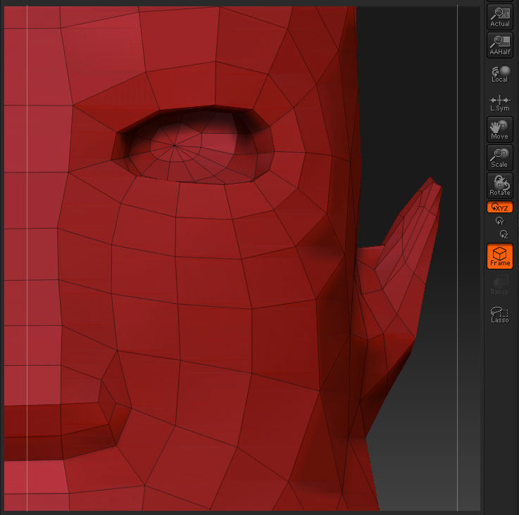
At first 2 images which showing the problem quit well.

[ATT=]z01.jpg[/ATT][ATT=]z02.jpg[/ATT]

The left image shows the broken topo and the right one the nice topo before switching to a higher subdiv lvl.

This happens in some cases of retopologizing and also happens when i switch to a higher reconstructed subdiv after retopo.

So why are this happen?

thx chew

Attachments

z01.jpg

z02.jpg

Just curious if you made SubD level ‘only when Adative skin has made’ or ‘add another level after adaptive skin has made.’
Also, the bad topo image looks to me it’s overlapped meshes… can you turn on ‘Dots Display’ to confirm that?

Rybeck

hi,

thx for the fast answer.

It is only one subtool so it can’t overlap.

Here is a view in “edit topology” mode.
[z03.jpg](javascript:zb_insimg(‘82885’,‘z03.jpg’,1,0))

after i press “a” for preview, the skin ist fine , no holes or something like that.

What’s the settings in Topology (i.e. PreSubD, Max Strip Length)?
Again, did you add extra level after you created Adaptive skin or not?

The lines not showing is a common display bug.

Try disabling edit-topo, then reenabling it. Or ctrl-drag a rectangle on the canvas ( topo lines can be masked ), and then looking at it. Or cloning the tool and then trying to edit topo again.

k these are the steps i do.

  1. i have retopologized my entire model. No display errors.
  2. then i make a polymesh of my adaptive skin and project all my details to the retopologized model.
  3. i reconstruct the sub divs. If i hit the “frame” button, Subdivision level 1 stil shows a nice topology .
  4. then i switch to a higher subdivision lvl ( the reconstructed ones) per example 5. and now my topology is damaged , even subdiv lvl 1.

so what can i do to fix that ?

the second problem is that i have no symetry. Even when i use “local symetry”.
I switch to subdiv lvl1. I mask one half of the model. then i push the “smart resym” button in the deformation panel but nothing changes and i get the error “symetry result: 0% symetry points found. Symetry map was not stored.”

what else can i do ?

EDIT:
images explain more than thousand words :slight_smile: .
[z04.jpg]

greetz chew

about the polyframe issue, at your lowest subd level, export and then reimport and obj.
about the symmetry, you may want to try these things but no guarantees.
try enabling uv’s
add a center edge loop
unify
also make sure in the preview window your model is oriented on the correct axis for symmetry


"Reconstruct Subdiv
: Given a model being displayed at its lowest subdivision level, this attempts to construct a lower-level model such that subdivision of that model would give the model currently being displayed. If this is successful, the displayed level 1 model becomes the level 2 model, and the newly created model becomes the level 1 model. Reconstruction of a lower-level model cannot always be done."
*Source:http://www.zbrush.info/docs/index.php/Tool:Geometry_Subpalette

I’m wondering if you can use ‘projection’ instead of ‘reconstruction’ unless you have particular reason to use it…

Rybeck

thx for your fast answers :slight_smile:

@rybeck : i am confused :slight_smile: i dont understand what you wanna say.

@spaceboy:

  1. i exported subdiv lvl 1
  2. then i load the obj into zbrush. And i load my highres ( subdiv lvl 5 ) model.
  3. then i append the highres model to the lowres imported obj.
  4. the highres model is very small so i resize it to the full size ob the lowresobj model. If i use the deformation>size panel then zbrush crashes (i think thats a known bug? )
  5. after that i clone the highres and lowres model
  6. then i take a zsphere , under rigging i use the highres cloned model and under topology i use the lowres cloned obj model for the topo.

Did i make a mistake ? The result is this!
[z06.jpg](javascript:zb_insimg(‘82955’,‘z06.jpg’,1,0))

now i test the “edit center edge loop methode” to fix the symetry.

“Projection” over “Reconsturct” idea was coming after I watched following video tutorial.
http://www.veoh.com/videos/v1107274r38q3GFB?c=nickzArtTraining

Steps would be…

  1. Export level 1 from detail mesh as OBJ (i’ll call it LOW_OBJ)
  2. Load LOW_OBJ (before doing this, I’d rather select the “Simple Brush” in order to avoid ZB replace ‘detail mesh’ for LOW_OBJ as current Ztool)
  3. Select ‘detail mesh’ and draw on workspace
  4. Enter Edit mode
  5. Select Zsphere
  6. ‘Rigging > Select mesh’ then select ‘detail mesh’
  7. ‘Topology > select Topo’ then select ‘LOW_OBJ’
    From this point, if you have no Scale issue (mismatching meshes), you are good to go for next step…
    Next step would be ‘projection’ and I believe you can get a grab from NICKz’s video…

Rybeck

thx for your efforts rybeck. Users like you should be in every forum . Many guys make posts like “RTFM ******”

I already viewed nickzucc videos. But i haven’t the time jet to retest the hole process.

I now know the “broken topo” is only a display bug or something like that.

greetz chew