ZBrushCentral

Rendering ZBrush Displacement-Maps In External Renderers (May 9th: 2nd file added)

Ok no more guessing… Here’s a way to calculate alpha gain and alpha offset at least for mental ray for Maya… It should work with most packages though :slight_smile: at least the way to calc alpha offset

Quick fix:
If you don’t need to understand what the problem is and how the solution works here’s the values in short

Alpha gain: (Alpha Depth Factor from zbrush * 10) * 2

Alpha offset: the negative (the inverse?) of half the alpha gain.

Example:
Zbrush Alpha Depth Factor = 0.834
Maya alpha gain = 16.68
Maya alpha offset = -8.34

An alternative to using this method is using the set range node and the multiply divide node.

Don’t change anything on the file node.
Connect the out alpha from the file node to the value x in the set range node
Use these settings for the set range node

Min: -1
Max: 1
Old min: 0
Old max: 1

Connect the outvalue.X from the set range to input1.x on the multiply divide node
Connect the outvalue.x from the multiply divide node to your displacement.

Now instead of changing the alpha gain when we want to scale the displacement, change input2.x value on the multiply divide node.

These methods will give you the exact same result but the one using set range is a bit less math.

Now for the ppl who just need to know (like me) :slight_smile:

The reason ppl have been getting “bloated” result is because the midpoint or the “no displacement” color of maps made by zbrush is 0,5 or gray instead of 0 or black

THIS HOWEVER IS NOT A BAD THING

Why? Because when modeling in zbrush you are quite likely to push your model inwards, creating negative displacement. If we wanted to get these negative displacements into a map while at the same time having the no displacement color at 0 (black) we would have to have negative color values. This is not supported by any image format I know of. This is why the makers of zbrush have decided to set the zero displacement color to 0.5 or gray.

So what to do? Well you could split the map in one negative and one positive displacement map by using Photoshop to save out al the values above 0.5 to one map and the ones below 0.5 to another.

How ever this poses a new problem and that’s how to get to displacement maps onto a single object. I didn’t find any way to do this in Maya so another way had to be found.

Something that is less that obvious in Maya (and mental ray) is that the displacement node actually can displace negatively. If you want to see for your self add a displacement material without any texture and set the displacement to a negative value. The whole object will shrink.

So what we need to do is subtract half of the values that we got from the map, simple enough just set the alpha offset to -0.5 and you’re done right? Well kinda.

The way alpha gain and alpha offset works is the value from the map is multiplied by the alpha gain and then added to the alpha offset.

Example:
If the value from the map is 0.5,
The AG is 1
And AO is -0.5
The out value would be 0.

This is what we want. Gray in the map is now zero displacement. But what happens if we change the alpha gain?

0.5 from the map
AG is 2
AO is -0.5

(0.5 * 2) - 0.5 = 0.5

Woops… Now gray in the map means a displacement of 0.5. When using AG of 2 we must subtract another 0.5 using the Alpha offset. So for gray to be zero displacement we have to set the alpha offset to -1

This means that the relationship between AO and AG should be
Alpha offset = -(alpha gain/2)

Now we have one more problem. Let’s say we have these settings
Value from map: 1
AG: 1
AO: -0.5

The out value will be 0.5 not 1. To fix this we double the AG and change the AO accordingly.
So:

AG: 2
AO: -1

Now we’ll get an out value of 1 when the value from the map is 1, we’ll get an out value of 0 when the map says 0.5 and we’ll get an out value of -1 when the map says 0.

And that’s all folks :wink:

well my therapist will be dissapointed not recieving a check from me each week, but will be relieved not hearing about displacement map issues from ZB2 to Maya.

Thanks for the details!
I can’t wait to try it out.
:slight_smile:
:+1: :+1: :+1:

Ok guys please help me :confused:
I have changed the map in photoshop to 16 bit RGB tiff anf flip it verticly.
You can see my settings in the picture.
What am I doing wrong? can any one give me the setting for basic render in MAX6 ??
and please be specific.

THANKs TO YOU ALL

Junk,
Here is a link to the scene. It will render quicker with GI off, but looks a lot cooler with it on.
http://www.arabian-archaeology.com/VRay/DispTestHead.zip

…your using the wrong displacement. Look up “displace approximation.”

thanks bisenberger
I sadly notice we have the same bug at the same place.
Border seams (visible above the eye)
Seems Vray is not able to render displacement map correctly or is it ZB exportation taht s bad?

Hi Junk,
Can you post one of your renderings and indicate the border seams. I don’t notice them on the image I uploaded.

Is there some new Infos about the Import/Export-Plugin?

Wow - Many answers.
I think many People want this Plugin :slight_smile:

For LW users.

After experiencing a lot of issues with the 16 bit tiff file and contacting Lynx. I tried using Fusion to generate a 16 bit Open EXR image without letting Photoshop damage the file in any way,

I used the Open EXR loader for LW from Flay to get the image into LW as 16 bit.

The Open EXR file used as a displacement, bump displacement or lynx’s normal displacement all produce spectacular results.

The settings required for all three methods are bascially upping the texture values respectively.

Currently Lynx’s 16 bit loader cannot open a Fusion generated 16 bit tiff file, hence the need for another file format.

Marious S.

X

Are there any News about this Plugin ?
Or maybe a surprise for siggraph2004 :slight_smile:

:grimacing:

Ofer,
And any Poser5 users.
I hope this isn’t too late but I have been ultra busy… here are the settings for Poser5 w/5.0.4.321 update patch:
First the Alpha had to be brought back into ZBrush and split into the Positive and Negative maps using the Alpha adjustment curve as stated earlier in this thread. Before you export these as 16 bit .tifs make sure the EP(Export Processed Alpha) button in the Alpha palette is pressed, and also flip the maps vertically.
Import these displacement maps into Photoshop or similar image editor and save them out as 8-bit tifs.
Next bring them into Poser 5 and while in the Material room create a math node with “add” as the argument. Set value1 to 1.00 and make a new node for it… a 2d image map node. Import your positive 8-bit .tif as the image map. Now set Value2 to -1.00 and make a new 2d image map node for it. You guessed it, import your negative 8-bit .tif as the image map.
Set the displacement value in this case to 8.34
Goto the render options and use the firefly render with 8.34 in the minimum displacement bounds box. Play with the rest of the settings to get an optimum render.
This latest update makes some parts of my tutorial on Displacement maps and Poser5 obsolete. The tutorial I’m talking about is found in the Z2 Practical Guide. I wrote the tut while z2 was still in Beta.
Oh well, at least it works better now,
Michael
Edited
Upon further examination it seems that I am getting an orange peel effect when using this solution. I am trying to convert the 16bit tif to other file formats but haven’t had any luck so far… Poser5 does not accept 16 bit tifs at all.
I hope we solve this soon!

Image render from Poser5 Firefly raytracer.

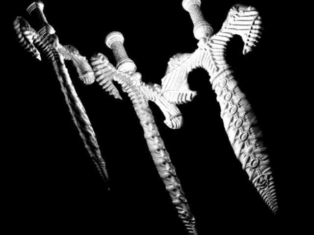
Here is a nice result of the sword, rendered in turtle with the following settings:
subd level = 3
displacement scale = 10
HDRI Image for light and reflection
original rendered at 2k*2k

render time unfortunately is very long, but quality is high.
Note - the model is the second sword model, with higher initial poly count.

sword 3 dif meshsmooth (none,1and2), all using max4, displacement approximation,high setting,fliped the map in Photoshop and ajusted the contrast.apply the displacement in the material slot and set to 12.

3swords

Attachments

3swords.jpg

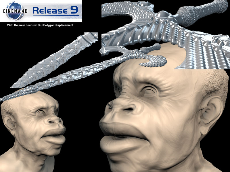
Great ZBrush with using C4D-Rendering:
Import, load Dispmap to Displacechanal.
Material must Flip Y.
SubPolygonDisplacement activate. Sublevel 4-5.
Render: (40-60 Sec. on P4 3Ghz 1GB)

SPD-Rendertests

Attachments

SPD-Rendertests.jpg

…seems to be even a bit more subtle:

Render time on my completely outdated Mac Cube 17 Minutes, which translates to ~1,5 Minute on a modern G5 or Pentium.

Pretty cool stuff :wink:

BTW: The texturemap needs to be flipped vertical to match. after looking through this thread this seems to be the fact for most software products anyway…

KabeSPDtest1.jpg

Rendered in XSI 4.0 with P4 2.8G 1G RAM : 30 Sec.

Great Forum and Z2 rocks !!!

2dragonz_Test

Attachments

2dragonz_Test.jpg

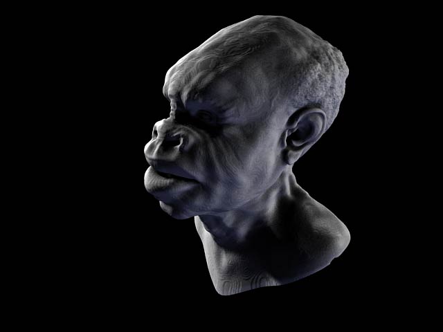
prman: maya - rat. using a basic clay surface, and a remapped image for the displacment. still working out the kinks…

-sunit

pixTest_0_1

Attachments

pixTest_0_1.jpg

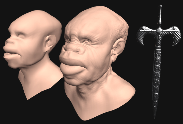
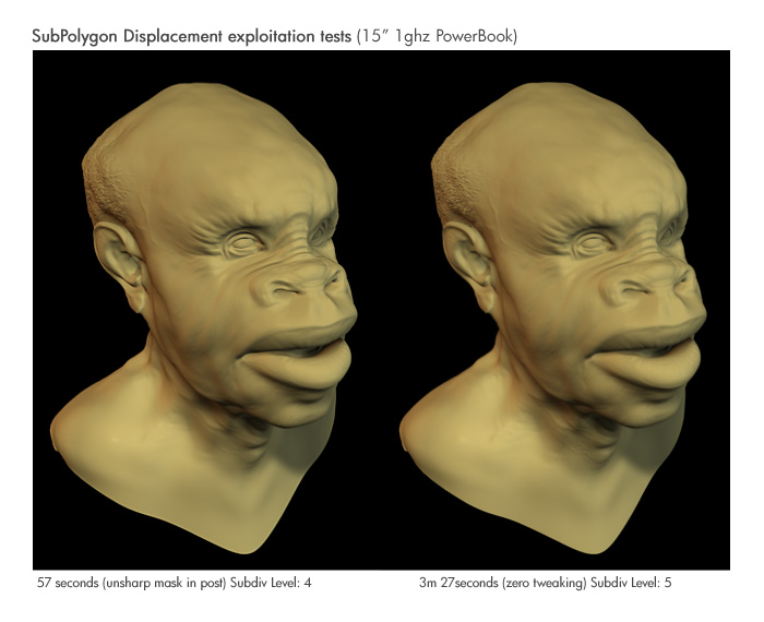
Just seeing how well a Unsharp Mask post tweak stands against a higher density SubD displacement mesh.

I need to try a few more angles…but ya know me…I like pushing it.

c4d9_tests

Attachments

c4d9_tests.jpg

First entry with Cinema’s new sub-polygon displacement! Fifty seconds at subdivision level 5:

I did these 2 images, the first is using the default scanline of 3dsmax 6, with a displace modifier applied above a Meshsmooth with 3 iterations and a UVW Unrap (I used MAX’s scanline 'cause I installed WinXP w/SP2 and I can’t install Vray 1.093 on it anymore…), and the 2nd was made with Vray render and Vray displacement modifier, 2D mapping, when it worked on my PC (by the way anyone knows how to make Vray work on XP SP2?? in pvt plz).

Seeya,
LSD
http://lukie.org
http://lukie.org/blogdisp_test_scanline01_lr.jpgdisp_test_vray01_lr.jpg