ZBrushCentral

Painting Aircraft Models

Hi,

I’m sure hoping someone can help point me in the right direction…

I am a programmer / web developer and I work for a small company that develops software for airports related to airport noise.

One of the programs we have developed flies 3D models of commercial aircraft in a 3D scene around the airport. The models used by the software are wavefront .obj files.

The company purchased ZBrush2 and Lightwave and asked me to use these programs to create various ‘skins’ for each of the aircraft models. The ‘skins’ are basically paintjobs that can be applied based on the airline (American, Delta, Continental, etc.).

I don’t have any experience with any software like this, and I’m trying to read and learn but I’m having a heck of a time. I have purchased and watched Meats Meier’s Introduction to ZBrush, but there are a few specific things I’d love to get some feedback on.

First - Is there a way to have ZBrush use a wavefront .mtl file to place various .bmp images on a model?

Second - When I create a new texture if I use the Projection Master and paint the entire aircraft a solid color everything looks good. But if I then try something simple like painting a colored circle on the side of the aircraft when I ‘pick up’ the object from the Projection Master the colored circled ‘smears’ or stretches and gets all funky shaped. How can I paint details on the model that remain crisp and clean?

Any help would be GREATLY APPRECIATED!

Thanks,
Rob

re: .mtl files.

No there isn’t but in truth you don’t need to use these to do what you want in ZBrush.

Regarding precision texturing (and texturing concepts in general) Go to the Tutorials forum and search for “Precision Texturing: Part 2”. Aurick’s explanation is clear.

If I can put it in a nutshell and many have tried

A 4 pointed polygon (defined in XYZ) has corresponding points that represent points in texture space (UVW) of which normally on U & V are used (because textures are usually 2D bitmaps). The computer keeps these in close association and draws both simultaneously. The shape and the texture that gets applied are thus mapped. It is important that your models have sensible mapping (so that a large shape isn’t mapped to a single pixel in texture space). You can reassign mapping in ZBrush using the tools texture modifier.

Check out the Precision Texturing tutorial and see how it goes.

Rob, it will take you a while to get familiar with all of this. Nothing wrong with that, just don’t calculate any deadlines…
Cheers
Lemo

honestly, if i were you I would just do the UV’s in lightwave, then texture the planes in photoshop. Unless you’re painting dirt and carbon stains and things like that, I think photoshop would be a lot better suited for decal placement, rivets, that sort of thing.

I have been using zbrush to texture planes.

I find that if I paint the base texture then for the decals such as company name or tail numbers or such I use zapplink and place those in photoshop for crisp details.

For panel lines and rivets I have been using the bump viewer material and custom alphas created in photoshop to place those in zbrush.

Hopefully that helps a lil:D

Thank you all very much for the responses!..

I will go find the tutorial that was mentioned immediately after I make this post.

As far as using Photoshop for the details… Does this tutorial go into how to do that? If not, can someone point me to instructions on how I would use Photoshop to paint a model?

Thank you again for your quick responses.
Rob

Hi Rob,

If you’re just getting started with texturing in LightWave, I would stronly recommend picking up Leigh van der Byl’s Texturing book. It will go a long way towards answering answering your basic texturing questions.

http://www.amazon.com/LightWave-Texturing-Wordware-Graphics-Library/dp/1556222858/sr=8-1/qid=1171033646/ref=pd_bbs_sr_1/103-6570787-1654223?ie=UTF8&s=books

If you’d rather not read through an entire book, you should check out the texturing tutorials on NewTek’s site:

http://www.newtek.com/lightwave/tutorials/index.php

Also, the LightWave Tutorials on the Web site has links to many outstanding texturing tutorials, including aircraft texturing tuts.

http://members.shaw.ca/lightwavetutorials/texturing.htm#Image%20Mapping

Lastly, my good friend Kevin Phillips has an outstanding video tutorial on texturing a Battlestar Galactica Viper which is available through Kurv Studios. It would be a great place to get started.

http://www.amazon.com/LightWave-3D-Advanced-Texturing-Rendering/dp/B000MMLMLW/sr=8-2/qid=1171033827/ref=sr_1_2/103-6570787-1654223?ie=UTF8&s=dvd

I hope these resources are helpful. Feel free to email me if you have any specific questions on working with LightWave.

Cheers!

Steve

Steve,

Thank you for the references. I will begin going through them…

I visited your sight and am going through the “There and Back Again: A ZBrush Primer for Users of LightWave 3D” tutorial. First, I’d like to say you do a really good job of explaining things!

I have attempted to go through the steps in the tutorial with a couple of different .obj models that we have purchased. However, when I get to the part about subdividing the model my models get gaps and holes in them. Is this an issue with the design of the model itself? I’m assuming it is. And is there anything I can do about it? Here’s a grab of the ZBrush document that shows one of the models after I have clicked the ‘Div’ button several times:

A340_DivideResults.jpg

I will continue to go through the rest of the tutuorial as well as the much of the other references you provided…

Thanks again for your help,
Rob

Well, in your case- you don’t want to subdivide so much as you want to tesselate. And if your model is going to be seen in a realtime 3D viewer, you don’t even want to do that (unless the 3D viewer is capable of pushing a LOT of polygons).

Hi Rob,

Thanks for checking out my site. It’s in a bit of disarray as I’ve been working feverishly to finish off Essential LightWave 9.

There are a couple of “There and Back Again” tutorials on my site that were developed back in 2003 when I was just getting started with ZBrush. Be sure to check out the ZPipeline Guide for LightWave which is the most up-to-date document on working between ZBrush and LightWave.

http://www.pixologic.com/zbrush/education/documentation/guides.php

Also, if you’re interested, I’ve got a 4-part series coming out over the next few issues of HDRI-3D magazine. They augment the current ZPipeline Guide by going into further detail on the workflow, sculpting and texturing aspects of the program.

The procedures outlined in the ZPipeline guide are geared towards organic modeling. The guide assumes you’ll be using a low-resolution polygonal cage and then using SubDivision mode in conjunction with a Displacement map to recreate sculpted details in LightWave. Unfortunately, that’s not what you’re doing. You’re working with a rigid object that only needs to be textured. It doesn’t need to be subdivided.

The exact procedure for texturing your aircraft is beyond the scope of this post, but I’ll do my best to make some suggestions. If any of these steps aren’t clear, just let me know and I’ll try to fill in the details.

All texturing methods use the concept of “projection” whereby the image you want is projected onto the polygons of your object. There are two basic types of projections: Standard and UV.

Standard projections allow you to project an image as if it were coming from a slide projector which is positioned and oriented at a specific place in 3D space. For example, if you have a rectangular box shaped like a television screen and it’s facing you in the Back viewport of LightWave (which views objects in the X and Z axis), you could tell LightWave to project an image along the Z axis (just like a movie theatre projector) to cast its image on the box. Standard projections come in several varieties. There are Planar projections (perhaps the most common Standard projection), Cylindrical, Spherical and Cubic. Each of these affects how the image is projected onto your object. Check the LightWave Help file for more information on these.

UV Projections are different than Standard projections. Where Standard projections place a virtual projector in space and cast an image onto the polygons of your object from a specific angle, a UV projection sets up a virtual projector and shines its image on a secret place called “UV Space.” UV Space is independent and separate from 3D space. It’s a 2D space. It’s perfectly flat and it’s always square. In LightWave, you can view this “hidden” space by changing your Top, Back or Right viewport in Modeler to UV Texture, clicking on the T button in the lower-right corner of the interface and then using the pop-up menu in the lower-right corner to select a map to view (or create one if none exist).

Since UV space is a flat 2D space, it’s ideal for painting onto it in a program like Photoshop or ZBrush. But you’re working with 3D objects, not 2D objects. Therefore, you have to have a way to flatten your 3D objects and lay them out in a 2D space.

There are a variety of ways to “unwrap” your object (a process sometimes known as “skinning”). LightWave offers standard projections and an object-oriented technique called “Atlas.” ZBrush offers standard projections and some unique techniques called “Adaptive UV” and “Group UV.” There’s not a “right” choice for unwrapping your 3D object and laying it out in the 2D UV space. Standard unwrapping techniques or LightWave’s Atlas work well and can make the unwrapped object look fairly recognizable in the UV space. ZBrush’s Adaptive and Group UV techniques produce polygon layouts in the UV space that are barely recognizable in the UV space. That makes them ideal for working in ZBrush but less than ideal if you want to paint on your polygons in a program like ZBrush.

For your project, I’d recommend using a UV projection over a Standard projection technique. That means that you’re going to have to unwrap your model. Unwrapping your object is beyond the scope of this thread but there are plenty of tutorials in the links above on how to do this. Now keep in mind that if you only want to do your texturing in ZBrush (or ZBrush with help from Photoshop using the ZAppLink plugin), you can simply unwrap your object in ZBrush with the GUV or AUV techniques (look in the Tool | Texture menu).

Once your object is in ZBrush and it has a UV map, you can use Projection Master to paint your textures on your object. I would recommend rotating your object to a 90-degree angle (hold down the Shift key while rotating) so that you’re looking flat onto your model. Then make sure that you only paint on the polygons that directly face you. You’ll have to enter and exit Projection Master a number of times to cover all angles.

Texturing in Projection Master is beyond the scope of this thread, but there are plenty of great tutorials out there that cover it in detail.

When you’re finished texturing your object, you need to flip the texture in the Texture menu. This is necessary for use in LightWave because LightWave’s UV coordinates are aligned differently than ZBrush’s. If you don’t flip the texture (which will make it look bad in ZBrush), it will look completely wrong in LightWave. Once you’ve flipped the texture, you can export it as a PSD and then apply it to one of the texture channels in LightWave.

Now as for your model, it’s hard to say exactly why the holes are there, but my first guess would be that the object has “n-gons.” N-gons are polygons with more than 4 points. ZBrush can’t use objects with n-gons and will end up creating holes in your objects. A quick way to check for n-gons is to load your object into Modeler, open the Statistics panel (use the button at the bottom of the interface) and then switch to Polygon select mode (again with the button at the bottom of the interface). This will place the Statistics panel in Polygon mode. Look for a line that says “>4 Vertices.” If it’s white, it means that there are n-gons in your object. Press the “+” button to the left of this listing. This will select the n-gons. Then press Shift+T to convert the n-gons to triangles, which will import into ZBrush properly. (You’ll need to export the file as an OBJ from Modeler first.)

I hope this helps. Again, if you need more specific information, let me know and I’ll do what I can to help.

Cheers!

Steve

Steve,

Thank you for such a detail response and explanation…

I am attempting to look at one of the models to check for ‘n-gons’, but I don’t see a ‘statistics’ panel. The version of Lightwave Modeler that I have is 7.5. Does the panel you referenced exist in this version?

Thanks again for all your help. I really appreciate the detail of your answers and explanations.

Rob

Hi Rob,

You’re welcome! I’m happy to help. The Statistics panel should be there in LightWave 7.5. Tap the “w” key and it should open up. The functionality of the Statistics panel hasn’t really changed over the past several versions of LightWave so everything I’ve described should work fine.

The UV texturing options prior to LightWave 8 (and 9) were a little more troublesome, but it shouldn’t affect what you’re doing. (The main changes allowed for better handling of UV textures on subpatch objects.) Still, I would recommend upgrading to LightWave 9 if your employer will allow it. And if not, you should at least ask to purchase FPrime from Worley Labs. FPrime is a real-time renderer that allows you to rapidly adjust textures and lights to set the scene just as you’d like. Also, it provides outstanding Radiosity which will produce photo-realistic renders very quickly.

Cheers!

Steve

Steve,

I haven’t gone through the last tutorial you referenced yet. But I will be doing that shortly…

I am also going to find some tutorials on using PhotoShop to paint the textures…

The ‘W’ key did toggle the stats window that you mentioned. I was hopeful that the model was going to contain ‘n-gons’ and that I could ‘fix’ the problem with the information you had provided.

I’ll show you what I’m running into at this point and maybe there’s something else I should try…

Here’s a snapshot of the model imported into LW:
A380_LW.jpg

To me the model looks ‘ok’ in LightWave (of course I have no idea what ‘ok’ would look like). It also looks ‘ok’ when I first import it into ZBrush. But even after just the first time I click the ‘Divide’ button portions of the model go blank. And this happens on every model I’ve tried so far (only 3 so far).

I hope I don’t wear you out with my issues. I really appreciate all the assistance you’ve provided.

I’m going to go look at the tutorial you mentioned and try to find one on painting using PhotoShop.

Thanks again,
Rob

Attachments

A380_Stats.jpg

A380_ZB_Pre_DIV.jpg

A380_ZB_DIV6.jpg

Hi Rob,

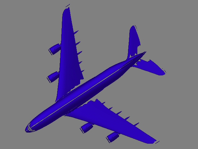
Hmm… Where did your boss get those objects? The model looks okay in the shaded mode, but the wireframe mesh is horribly triangulated. It looks like a low-poly version of a higher resolution object which has then been run through a Polygon Reduction filter. Ugh. Well, that will make things a bit more difficult but not impossible.

Okay, first things first. Don’t hit the Divide button. You don’t need to. The only reason to hit the Divide button is to add more polygons. More polygons are only needed if you want to sculpt details onto your mesh. (Sculpting involves the manipulation of the polygons which deforms the shape of your object. Painting (in this case) refers to the creation of texture maps which affect teh color and shading of your object, but not its overall form.) Since you only want to paint textures onto the plane, you don’t need more polygons. And therefore you don’t need to hit the Divide button. :slight_smile:

As an aside, the tearing you see when you do hit Divide may be caused by overlapping points that have not been welded or merged together. On a 3D object, points can occupy the same space, but that does not mean that they become fused together into one. Unless you tell the software to do so. If your plane has overlapping points (indicating areas that are not fused together), they may shrink when you try to divide the object in ZBrush. Try opening the object in Modeler and pressing the “m” key to bring up the Merge Points window. Accept the defaults (Automatic Settings) and press OK. A message will appear telling you how many points were merged. If it’s anything higher than zero, that may have been the problem.

Okay, since you don’t need to Divide your object, you can simply use ZBrush to paint the textures. The only problem is that ZBrush really prefers quad polygons (polygons with four points). It will tolerate triangles, but it really wants quads. In my experience, when I’ve brought a highly triangulated object in and tried to texture it, I’ve ended up with weird streaks that are nearly impossible to remove. But you won’t be able to tell if this will happen until you try it. So do the following.

In Modeler, click the T button at the bottom of the interface. This places you in UV Texture selection mode. Then click and hold the pop-up menu to the right. (It should currently say “none”.) Choose “New” to create a new UV. Set the Mode to Atlas. Enter the name “PlaneUV” and click Create.

Press the “q” key to assign a new surface to this object. Call it “Plane” and press Okay.

Open the Surface Editor and click on the “Plane” surface. You’ll see a list of surface attributes. The first should be Color. To its right shoudl be an E and a T. Click on the T. This will open the Texture Editor.

In the Texture Editor, choose the Layer type as Image. Set the Projection to UV. Then select the PlaneUV from the UV selection pop-up menu. Close the Texture Editor.

Go to the File menu and choose Export | OBJ to export the object as an OBJ file. This will save an object that ZBrush can use.

What you’ve done is created an Atlas UV map which should minimize any UV distortion (that’s a longer discussion) and you’ve applied the UV to the object’s surface which ensures it will load into ZBrush correctly.

Now you can load ZBrush and import the OBJ you created. Rotate it in ZBrush so that it is looking from the Top down. Then hold down the Alt key and click and let go in a blank portion of your canvas. This should size the object to the canvas.

Go to the Texture menu and enter 4096 for the resolution. Then click New. This will create a blank 4096x4096 image for you to paint onto.

Press the “g” key to open Projection Master. Select Colors and turn everything else off. Then click the Drop button to enter Projection Master. Once in Projection Master, you can use the variety of brushes to paint on your object.

When you’re finished, press “g” again to pick up your object. This will allow you to rotate it again. Rotate it so that you’re facing the side of the plane. Be sure to snap your rotation by holding down the Shift key. Then enter Projection Master and repeat the process.

If you’d like, you can use the ZApp Link plugin to gain the benefits of working in Photoshop along with ZBrush. Check the ZApp Link tutorials on this forum for more info.

When you’re finished texturing your object, flip the texture vertically by clicking the Flip V button in the Texture menu. Then export the image as a PSD.

Back in Modeler, open the Texture Editor for the Color channel. The Projection should already be set to UV and the UV map should already be selected. Click on the Image pop-up menu and choose “load.” Then load in the image you saved from ZBrush.

Save your model in LightWave. Then bring it into Layout. Adjust your lights and then render away.

If that doesn’t work, you’ll likely need to revert to using Photoshop. Try the links above for information on how to do that.

I know this is a lot of info to absorb. And this isn’t the most detailed of explanations (sorry!). But hopefully it should point you in the right direction. For what it’s worth, it’s highly unreasonable for an employer to ask someone with no 3D experience to sit down in front of two very complex programs and produce something. It’s not impossible, but I’ve been training people how to use LightWave for years and in my experience, it takes months to become comfortable and productive using the software. If you give yourself that time, I have not doubts you’ll be able to achieve your goals. So just keep that in mind when you feel frustrated and overwhelmed. There’s a lot to take in and it’s not easy. But it’s always worth it. :slight_smile:

Cheers!

Steve

Steve,

Once again I can’t thank you enough for the time and effort you put into your responses! I have had some people help me with issues in the past (in the programming / development world), but I’ve never had someone put so much effort into helpful, clear, understandable assistance. Thank you!

I am headed out this morning and probably wont be back until late tonight. And tomorrow looks like it’s going to be just about the same. So I probably won’t get a chance to perform the steps you detailed until Monday…

As a quick note: the ‘weird streaks’ that you mentioned are exactly what my problem has been so far. When I drop the model in the Projection Master it looks good. When I paint in the Projection Master it looks good. But when I pick the model back up (exit Projection Master) it immediately gets the ‘weird streaks’ you described.

I will go through the steps you described and let you know what happens. I just wanted to be sure to let you know how much I appreciate your help before I have to ‘disappear’ for a couple of days.

Thank you again for everything,
Rob

Hi Rob

Thanks for the really kind words. I’m happy to be able to help out. :slight_smile:

Since your object’s mesh is so garbled, it’s going to be difficult to paint it using Projection Master. You can try to clean up the mesh, but I think you’re going to find that it’s a losing battle. For this job, I would recommend using standard projections and using Photoshop to paint the textures. Below is an image that shows the basic process.

You’ll need to isolate the different parts of your object (i.e. the Fuselage, the Wings, the Tail, the Engines, etc.) and create different surfaces for each one. Then use the technique shown below to create textures for their top, front and side views. The technique below also shows how to blend the textures from each projection together to avoid stretch seam marks. The blending in this example is fairly noticable, but when you’re blending more similar looking textures the results are nearly invisible.

Cheers!

Steve

Steve,

Very interesting results…

I went through the steps you detailed regarding creating a UVMap in LW Modeler and then painting in ZBrush in the Projection Master. And to my surprise when I ‘picked up’ the model from the Projection Master everything looked really good! No weird streaks… I can actually export the object and the texture from ZBrush and use in our animation program with success. This is a great step forward because it enables me to paint in ZBrush.

But now I’ve been presented with a question/challenge by my boss. He wants to know if I can take an image (for instance a picture of the airline logo from the tail of an airplane) and in essence ‘paste’ the image as part of the texture on the plane. To this end I began going through the steps in your last post. However, I immediately ran into a couple of issues.

  1. I don’t know how to go about ‘isolating’ the different parts of the model. Do I do this by selecting points or polygons and making individual files of the various parts?

  2. When I tried holding the mouse over a viewport and hitting the numeric ‘0’ button the model seemed to disappear. I zoomed all the way out and all the way in and couldn’t see the model.

If you have the time to give some insight to these issues that would be great…

Also, is there a way to ‘paste’ an image in ZBrush (instead of using Photoshop)?

Thank you so much for all your guidance to this point. I am really excited that it appears I can at least have success painting directly in ZBrush.
Rob

Steve,

Just thought I’d post a couple of images showing progress so far. I did a really simple, quick and dirty paint job to test the process of creating the UVMap in Modeler, exporting to ZBrush and painting in ZBrush. Following is an image captured from ZBrush:

A380_capture.jpg

Attachments

BridgeXtreme_Capture.jpg

Excellent! I didn’t know if that would work with the mesh being so unruly, but I’m glad it did. Using an Atlas Map from LightWave is often the solution when ZBrush’s AUV/GUVs fail.

(Just a quick note: You can follow the steps outlined here, but since the texturing in ZBrush is working, you may want to skip these steps and see the info below on placing an image into your texture in ZBrush.)

The easiest way to apply surfaces to specific parts of your object is to select the polys in question and then change their surface.

Switch to Polygon select mode in Modeler (use the button at the bottom of the interface) then right-click and drag a lasso around the polys you want to select. You can hold down the Shift key to select additional polys or you can lasso select any currently selected polys to deselect them. Once you’ve selected just the polys you want, press “q” and enter a new surface name for them.

Hmmm… Once you go full-screen in a viewport, tap the “a” key to fit the object within the current viewport. If that doesn’t work, make sure you’re in a layer that has geometry. Look at the rectantular layer icons and look for a black divot in the upper-half. If that doesn’t work, press the “” key to unhide any hidden polys.

Yes! Sort of. :slight_smile:

Start by prepping your image in Photoshop. Create a 512x512 image and lay out the logo just as you want it. Then create a black and white mask in Photoshop to determine which parts should be visible. White areas will be opaque. Black areas will be transparent. Save out the color image as a PSD. Then save out the black and white mask as a PSD.

In ZBrush, enter Projection Master. Switch to the SimpleBrush. Load the color PSD into the Texture palette and the corresponding mask into the Alpha palette. Then change the Stroke to DragRect.

You can now drag out the image over your object. Once it’s generally in place, you can switch to the Move, Rotate and Scale modes to position and size it just how you want.

Technically speaking, you don’t need the Alpha image to get transparency in your textures. You can simply paint them over a black background and then turn on the Transparent button in the Texture menu. But in my experience, the results aren’t as clean as using a dedicated Alpha.

You’re welcome! I’m happy to help. :slight_smile: Your results so far look great!

This is a pic of the plane that I am texturing in zbrush.

For the decals I use the zapplink plugin that allows me to take the painted model from zbrush to photoshop and place the decals on top where I want as a new layer. The decals ae the navy insig, tail stripes and numbers.

I continue placing the decals with projection master and zapplink untill I am all done. The next step will be to create the panel lines and rivets with the bump material. I dont divide this model because I get the same model tearing and I am using a bump map not a displacement map.

Attachments

kingcolor.jpg