ZBrushCentral

Lightwave Displacement Problem

Hi guys,

Recently I’ve been learning about integration between ZBrush and Lightwave, so I stumble upon Steve Warner’s tutorial (its kinda old stuff, but still a great things to learn ;))

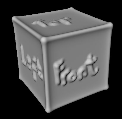
Normal maps seems no problem, but when I try to create a displacement map, things start to looks weird, you will see what I mean from the images below.

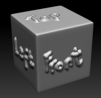
Here is the mesh inside of ZBrush…

box_ZBrushDispMap_Thumb.jpg

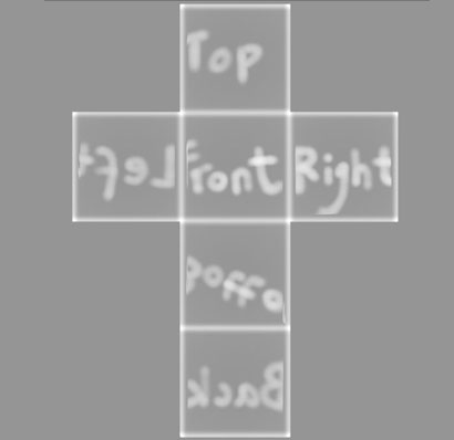
I dont know which part that I’m wrong, but I guess the edges in the Lightwave render was “inflate” because of the edges in the map is white-ish in color, that’s why it result like that. Displacing the geometry on its normal direction like the one of the “front”, “left”, “top” words…

Anyone have any other thought that can explain this situation?
Or if have a solution will be much better and appreciated :wink:

_Revel

Attachments

box_ZBrushDispMap.jpg

box_LightwaveWierdDisp.jpg

box_DispMap.JPG

Here is an extraction of a very helpful converstaion i had with steve a while ago.

Basically when it comes to Lightwave, forget about the displacement.

The basic pipeline from ZBrush is as follows (obviously condensed for brevity):

  1. Go to your lowest subdivision level in ZBrush and take a look at the mesh. It should look (for the most part) just like the high-res version, just without the fine details. If it does not, you should go up one (or two) levels and then delete any lower levels.

  2. Check your base polygon count. If your base (lowest subdiv level) has more than 10,000 polys, you should probably retopologize.

  3. Once you have an acceptably low poly object, make sure your SDiv level is at 1. Then go to the UV Map section of the Tool menu. Delete the existing UV (if any), set the resolution to something reasonable (like 2048) and then choose PUV Tiles to create a PUV map. PUV’s are like a combination of AUV and GUV and they produce excellent results.

  4. Go to the Normal map submenu. Turn on Adaptive, Tangent and Smooth UV. (If you find you get texture abnormalities, turn Smooth UV off.) Then generate the Normal map. It will be deposited into the Normal map bin. Click Clone NM to send the normal map to the main Texture bin.

  5. Open the main Texture menu and choose Flip V. Then export the map as a PSD file.

  6. Go to the Tool | Export menu and turn on MRG. Then go to the top of the Tool menu and export your OBJ file.

  7. Go to the highest SubDiv level for your object and then open the Tool | Masking menu.

  8. Generate a Cavity Mask or an Ambient Occlusion Mask. This will help the shading inside LightWave. You will see the mask on the object. When it looks good to you, press the Mask | Make Alpha button. The mask will be transferred to the Alpha bin.

  9. Open the Alpha menu and choose Make TX to convert the alpha to a texture.

  10. Open the Texture menu and (ensuring the converted alpha is selected), flip it vertically and export it as a PSD.

  11. Open Modeler and load in your exported OBJ file. Once it’s loaded, hit Tab to convert it to a subpatch object. Then save.

  12. Open Layout. Load in the LightWave object. Then open the Surface Editor. Click on the main surface and turn on surface smoothing towards the bottom of the General tab. Then enable Nodes (by clicking the blank checkbox) and enter the Node editor.

  13. Click the Add Node and choose 2D Texture > Normal. Double click the node to access its properties. Load the Normal map, turn off Mipmapping, set the Projection type to UV and then select the UV space (typically OBJUVTextureMap). Then connect the Normal output to the Normal input of your surface.

  14. Back in the main surface editor, click the T next to the Diffuse channel to open the Diffuse Texture Editor. Set the Projection to UV and the UV Space to the same one you used for the Normal map. Then load in your Cavity/Ambient image. This will work as your diffuse map. You may notice that in LightWave 9.6 your object goes black. Sometimes adding a diffuse map causes the main diffuse value to go to zero. Just set it back to 100%.

Hope that helps.

So, are you saying that Lightwave is not yet support displacement map generated from ZBrush correctly?..

But I think the error was just happened on the edges of the box. There must be some setting that i missed here, whether its when I created/ export the map from ZBrush or on the node setting value inside of Lightwave.

I will try to play around with some of the settings there and maybe try to use other object which more organic and don’t have hard edges (*I’m thinking about a ball right now :lol: pretty simple stuff just for experiment…) and will post the result after that.

dsoellbuster, thanks for the reply btw :slight_smile:

_Revel

Of course Lightwave supports Displacement maps, but in most of the cases they are just not necessary anymore.

The problem with Displacement Maps is that they are size dependent, meaning that depending on the size of your mesh, you need to adjust your displacement settings.

if you need any more help with that, just PM me.

Cheers

Dirk

No this is happening in Zbrush 3.5. I am getting this even when using Maya mental ray, Vray or modo. The white that Zbrush is placing around the seams is incorrect for a 16bit result.

Anyways, you have to save a morph target and switch back to the MT before exporting the displacement map OR use “crease seams” by shift clicking it before exporting displacement maps. I think Zbrush needs to have this setup by default as it is probably used more often then not But Crease seams only seams to work for non-organic cube type setups because it makes the problem worse on organic models in a different way.

There needs to be a no frills stupid proof expected result way to get displacement out of Zbrush. This used to be a no brainer, now I am spending hours trying to figure it out.

@dsoellbuster
What do you mean by “Displacement Maps is that they are size dependent”?..because even if I scale the cube inside Layout, the displacement following the scale (I guess its because the UV also following the scale)…

@Intuition
[Crease] seems won’t work on my cube either, after I switch back to the original MT and crease on all of my edges (by holding shift), it still give a weird edges (some kind of a black lines in the disp map) and some more it shrink the detail that I sculpt on.

Btw, does anyone knows how to set a UV resolution if I create it in Lightwave (or any other package, like Maya or Max, cus its probably the same flow)?..does it depends on how much polygons that I put inside the map?..because no matter how big the object is, the UV map still have to fit into 0 - 1 UV grid…

_Revel

Hey guys,

I just browse through the forum and found the solution for this problem, thanks to Intuition and his threads here, now the mystery solved. Just turn of the Adaptive and Smooth UV (Adaptive will adding white edges to the map, Smooth UV will shrink the detail that sculpted on the mesh) and everything -hopefully- will be alright. :slight_smile:

And about the how to set the UV map resolution that created outside of ZBrush question, I still not yet found the answer…
So anyone knows anything about it?

_Revel