Modeling
The model was mainly built with the polygonal modeling features of ZBrush and only a few sculpting brushes. The Topology Brush was used for some specific parts, ZModeler for the main shapes and all topology refinement, PanelLoops for a consistent thickness of each part, retopology of other parts using the ZSphere retopology tools, etc.
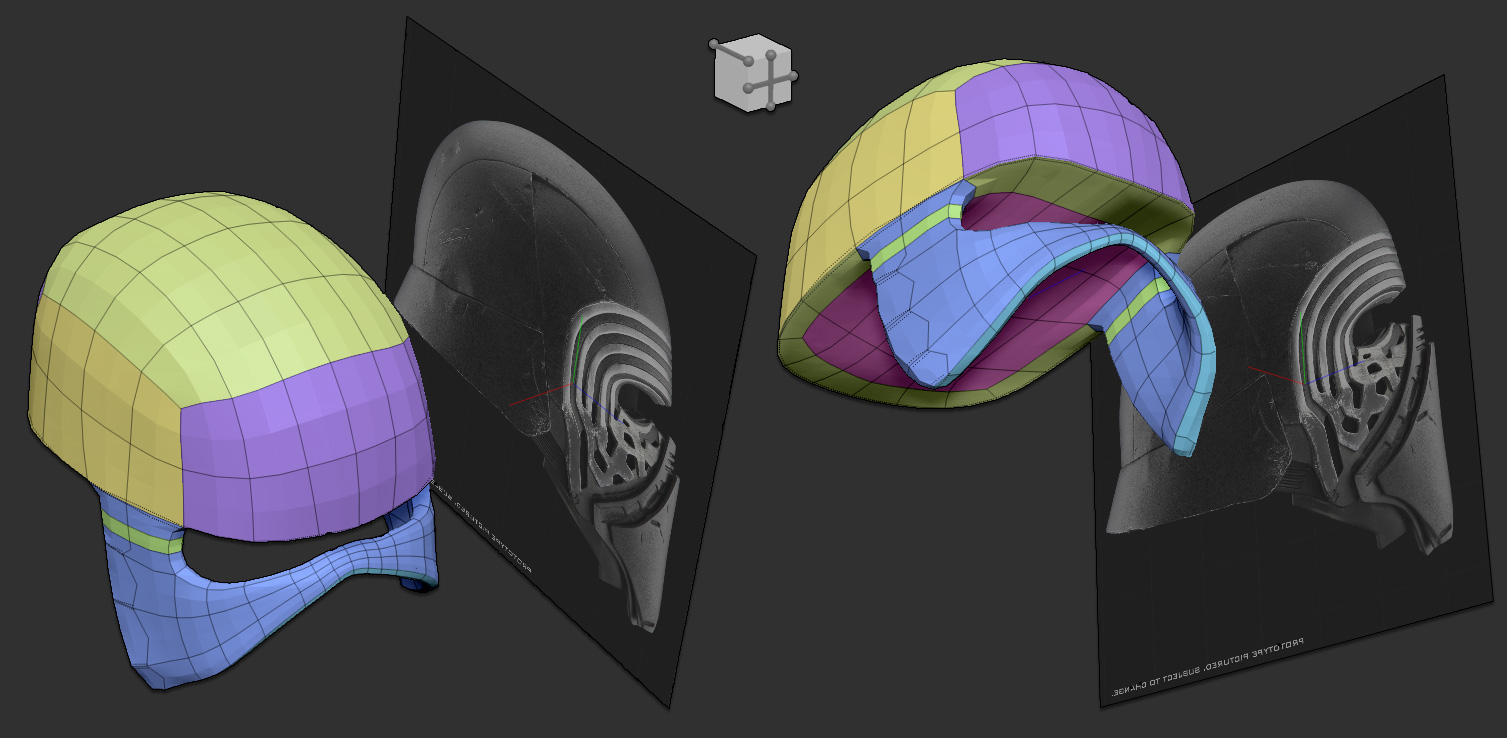
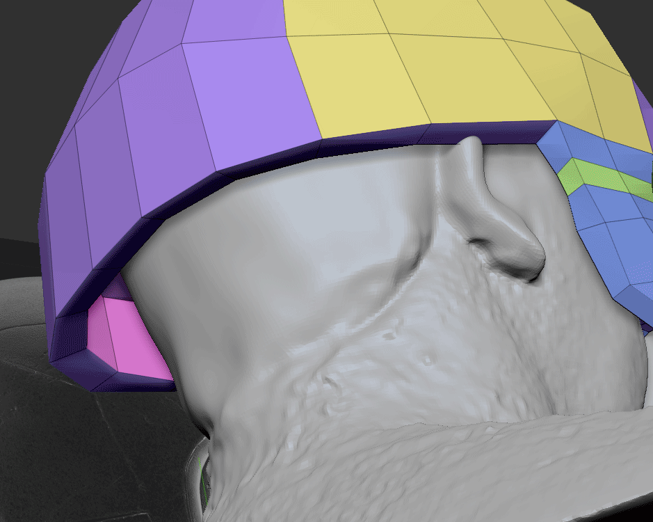
The first step was setting up the shape itself. By this I mean establishing the correct proportions within a shape that is both close to the original model and fitting the 3D scan. This is a crucial step because if you build the wrong foundations, your final print will be wrong as well. This step was therefore not a quick one but it was very important. Another benefit of working with a low polygon topology is the ability to manipulate only a few points with the Move brush to make shape refinements with ease.
Below is the beginning of the helmet shape which was started from a QuickCube mesh that I modified with the ZModeler brush. Notice the main reference image to one side, loaded onto the side Grid using the settings found in the Draw palette.
This first modeling stage was focused on getting me close to the original shape rather than building what would become the final parts of the model. That step would be done at a later stage.
The ZModeler Brush and its QMesh Action was what I used the most to build the shape. For the bottom-back part of the helmet, I only had to select a row of polygons with ALT, then use the CTRL key to extract a strip of polygons before extruding and tweaking them with the Move brush as shown in the animation below. Using the CTRL key lets you separate parts without leaving the brush.
After more and more such extrusions and point modifications, you can start to recognize the helmet – but only if you know the movie very well. At this stage, it would have been a mistake to start building details when the base shape was not yet well defined.
Refining the Shapes
There is one criteria that is important to keep in mind through the entire creation process: the final 3D printing process. You must never forget to ask yourself key questions: “How I will print this part?” or “Will it fit the 3D printer’s building volume?” This means that you must work with multiple parts from the start rather than from one block which would need to be split into multiple parts at the end of the creation process.
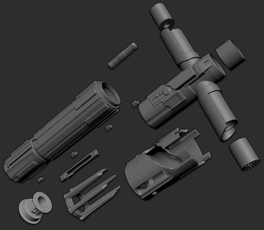
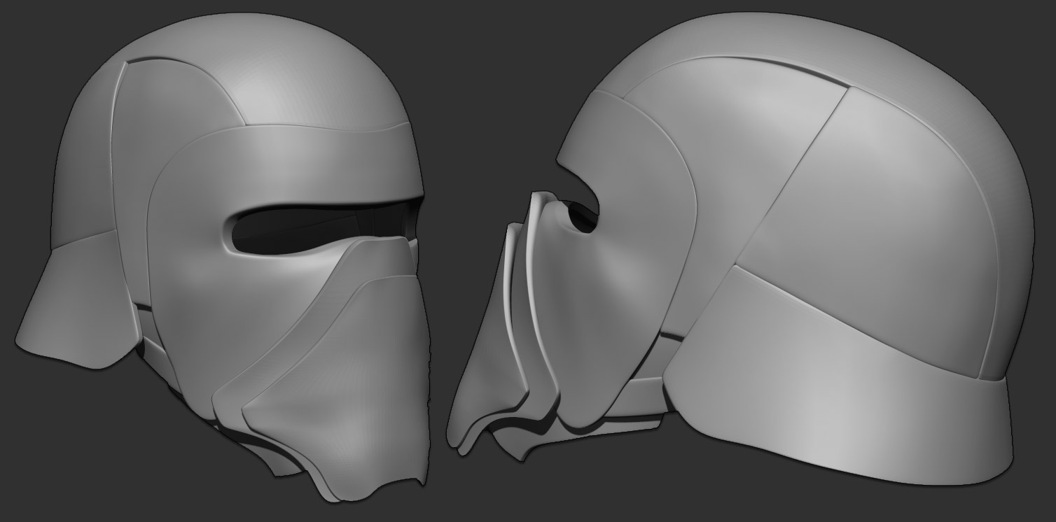
Before thinking of a final split, I decided to go with each visual part of the helmet. For Kylo Ren’s helmet this was fortunately very well defined with side, top and back plates, a front grid and also front shapes for the mouth area, etc. Thanks to its design, it would be easy to hide the splits between parts such as what I did for the shape behind the chrome grid.
One last thing that I had to consider: How would I bring this helmet on a trip from France to Los Angeles? There would be no way to have such a helmet in the airplane cabin and it would also be rather big to fit in my luggage. I decided to build it in two parts: One for the front part of the helmet (the face) and a second section for everything else. I then planned to use strong magnets to fasten the two parts together.
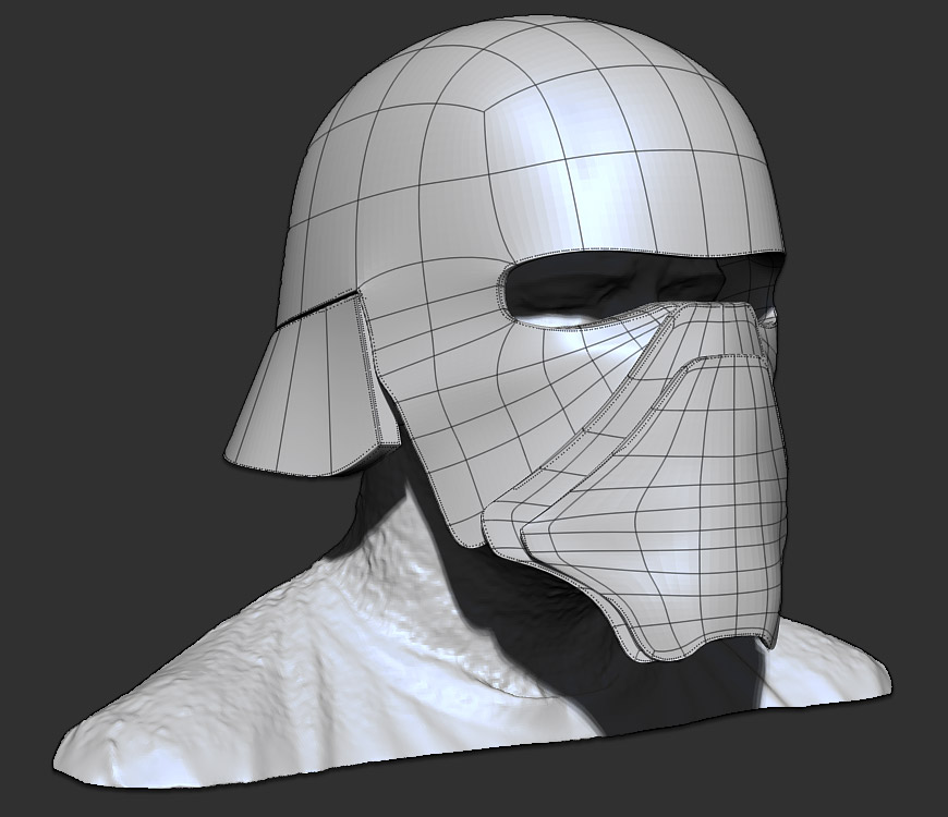
As you can see in the screenshot below, building all these parts wasn’t very complicated. It was always the same process except to add some extra edge loops in order to control the boundaries and ensure nice connections between all of them.
I built each part separately using mainly the Topology brush. Then it was only a matter of copying the shape on top of the foundation that I’d built with ZModeler earlier. Below you can see the creation of the front part of the helmet, where I used the Topology Brush to do the loops and polygons. It’s quick to do and because the output is 3D printing, I have way fewer constraints than animation or real-time models when it comes to topology flow.
As you may know, the Brush Size radius will set the thickness of the model generated from the Topology brush. For this project, I generated surfaces without any thickness by setting my brush size to its minimum. This let me modify only a few points to adjust the shape without trying to deal with the thickness or deforming the front and back parts of the surface.
Once all the surfaces were generated with the Topology brush and tweaked with the Move brush, I then proceeded to generate thickness for the shapes.
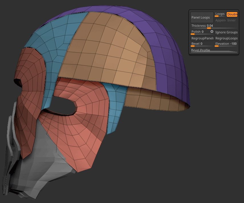
This stage was very easy and can actually be done in multiple ways in ZBrush. I wanted to use a process which would let me have a uniform thickness throughout. Panel Loops (found in Tool >> Geometry >> Edge Loops) lets you do that by adjusting only a few settings like no Loops, no Polish and negative Elevation. This resulted in the same thickness for all the panels as shown below.
Again, I did some verification with an eye for 3D printing, always thinking about the helmet’s size how it would fit my head.
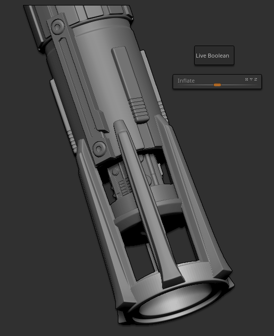
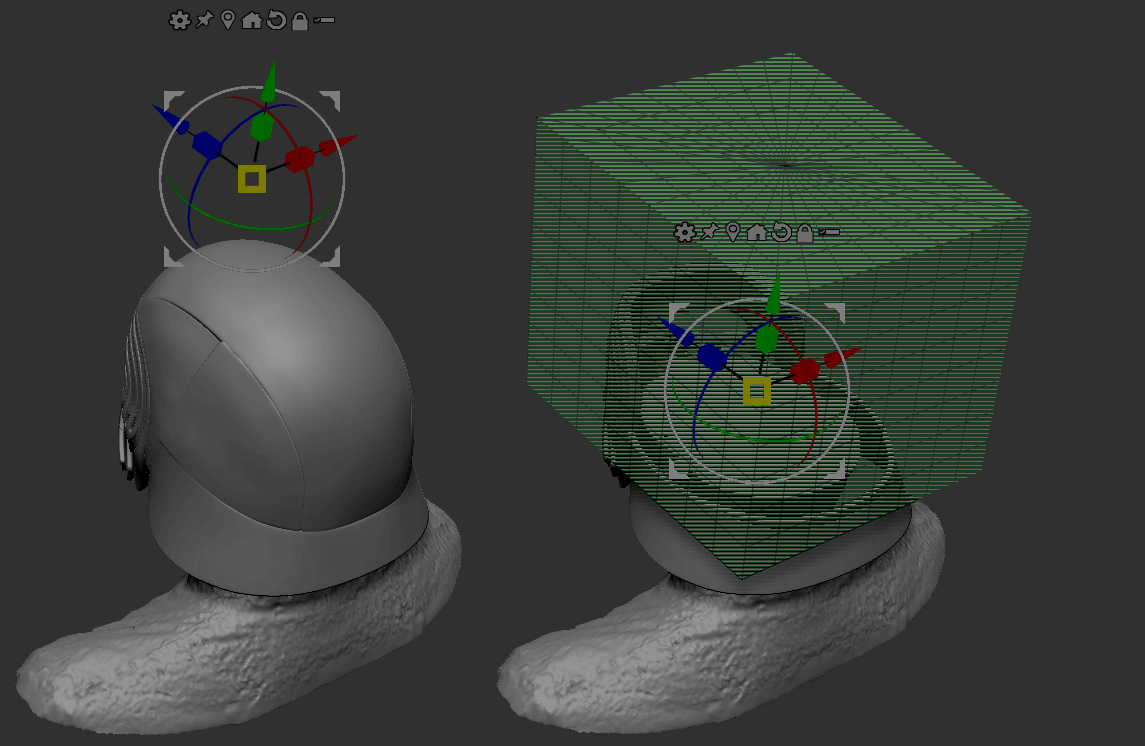
Thanks to the Live Boolean feature, I could simply use a cube set in negative mode (on the right, below) and move it up/down to visually slice my model and see if I had any intersecting surfaces. I could then refine the model as needed and in real-time.
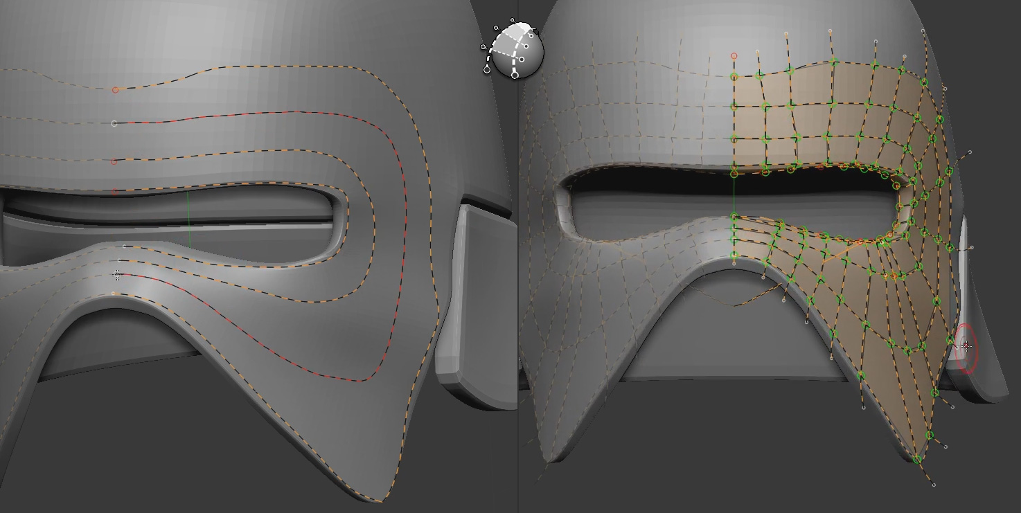
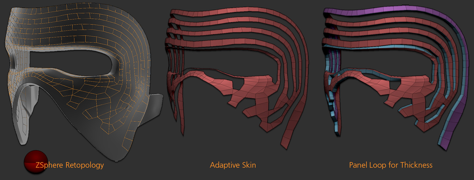
To build the chrome grid on the front of the helmet, I once again did retopology. This time, however, I used ZSpheres. It may be an “old” way of building but I’m from the old school of polygonal modeling, having been an edge modeler for years. Working with ZSpheres gives me very good control over my topology.
Once the topology was done and generated as an Adaptive Skin, I applied a Panel Loop.
It was then time to start refining the shape and more importantly, build the parts closer to what they would be at the end.
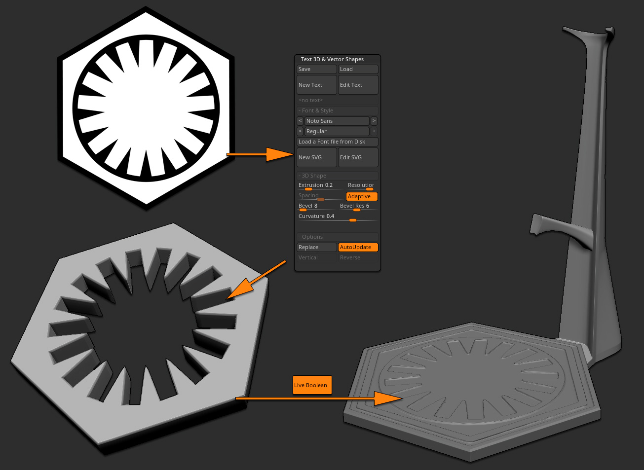
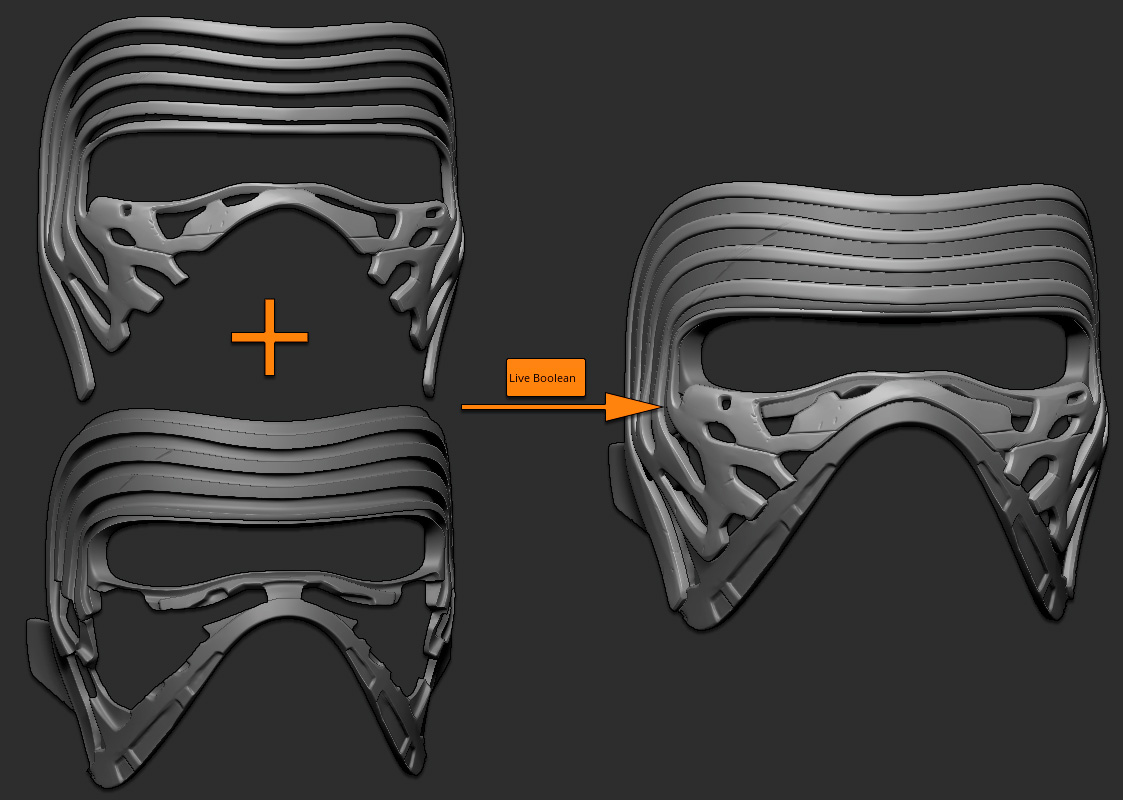
Below is an example of the grid. With the help of Live Boolean, this was used as a negative mesh on the support of the front part of the helmet. By adding a positive copy of the grid, I now had both parts.
Regarding the negative part used with the Live Boolean, I applied a small Tool >> Deformations >> Inflate to create a minor gap between the negative and positive parts of the mesh. Such a gap is necessary in order to ensure that assembly would be flawless after having the model printed. If the positive mesh (the grid) was too thick, it would be impossible to insert into its support or would require a lot of sanding and other post work. 3D printing can take a lot of time and (depending on the material used) can be quite expensive. It is therefore always important to do one’s best to anticipate and eliminate potential issues.
For the eye grid shape it was actually a lot easier than I had expected, thanks to multiple ZBrush 4R8 additions:
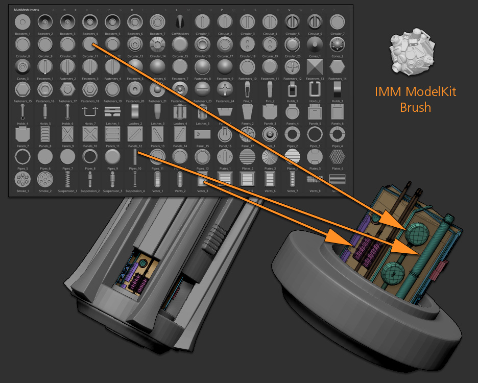
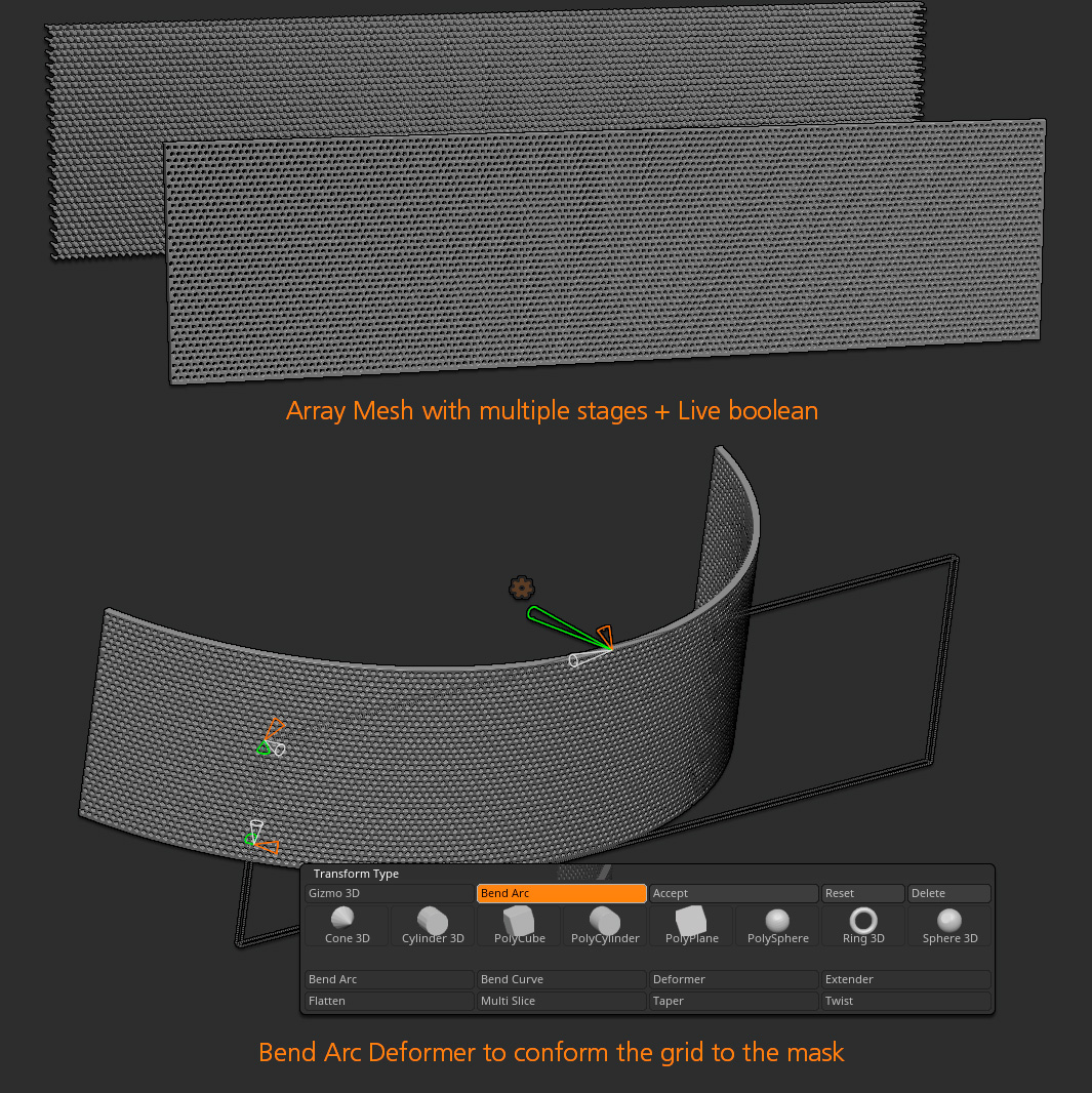
First, I built a series of cylinders as using an ArrayMesh composed of three stages. The first stage created a row. The second stage copied the first stage’s result, but with an offset on the X axis so that they wouldn’t be aligned. The third stage duplicated both results multiple times. I really love the ArrayMesh because it is fully parametric.
I then used this ArrayMesh result as a negative mesh on a rectangular volume to create the grid shape itself.
The last step was to bend it as a kind of half circle. For this the Bend Arc deformer found in the Gizmo 3D was perfect. As an alternative, Bend Curve could have done the job. Some refinements with the Move brush (and a large Draw Size) finished the job.
Attachments