ZBrushCentral

Rendering Zbrush Displacement Maps in Maya

zkanal: OH, I understand what you mean, the flickering of coplanar faces.
Thats a great idea to use during test renders. I usually start my renders with a very high number and if I notice problems in unaltered areas of my model then I know off the bat I need to address other issues.

On the 50% gray question I suppose it is better to say that Zbrush generates a map where the midpoint of the map is no displacement as such the remapping of values from 0 to 1 to -.5 to .5 will still work.

Zbrush generates the map to make full use of the range of values available in a 16 bit map.
Here is a great thread about this where Pixolator posts a test to explain how zbrush makes use of the full range within the map.
http://www.zbrushcentral.com/zbc/showthread.php?t=23573

Scott

Try it … I for one can’t get 100% accuracy with the 50% thing… I always have to set my value to the exact grayscale midpoint value…
However my workflow seems a bit different than any other I have seen for ppl using zbrush and maya … I use utility nodes hooked up so that when I raise alpha gain my alpha offset scales accurately with it.
And regarding measuring the color with ps, I do not… I use DFX+ which gives me a totally different reading.

ZBrush always creates displacement maps with 50% gray as the zero point. If you have a map where the mid point is a different shade than 50% gray, please check the photo editing software that you opened the map in. You most likely have a setting enabled that allows the software to manage colors for you when you open a file. This means that the program you’re opening the map with is changing the colors on you. Once you disable that setting, you will see that the ZBrush map is indeed 50% gray at the mid point.

But I have no color management in DFX+ and it still reads somewhere near 50%, but not exactly 50%… I can hopefully post some screens.
Now I’m puzzled, anyway… I always get totally correct displacements, so I must be doing something right I guess…

A very good thank :slight_smile:

It would help me :wink:

I used this technique and it works perfectly, but i had holes in my mesh on the render image and i don’t understand why ?
Thanks for your help …

When I see artifacfts like that I usually smooth my mesh with Polygons>smooth or increase the subdivision approximation settings.

You can also try smoothing the edge normals but usually this seems to mean that the map is breaking the mesh because there are not enought subdivisions to support the level of displacement it is attempting.

I hope this helps,

Scott

Thanks :wink:
The holes had disapeared with the smooth but the next time i tried to not have tris or 5 in my mesh …
PS : Sorry for my bad english but i’m french :lol: :smiley:

yo Elendil and Scott,

this brings up a really cool trick to know about -for all you hamburgers and cheese-burgers out there: lots of folks get fustrated cuz they can’t finish there model with just quads. and mentalray likes either all quads or tris for subdivs. if you use a polysmooth node before the subdiv approx you can use any nsided polygon you want – maya will make everything quads before it gets to mr. if you’re animating you can apply the polysmooth after the rigg is done so you don’t loose the base mesh.

that said – keep trying to learn how to use just quads - imho

Thanks for teh tips :wink:

Scott, thank you very much !
I just give that Video Tutorial a try and …first time ever rendering ZB2 Displacement map inside Maya and I got very good results !

All I need now is to try make original “thing” to see how it works.

THANK YOU SO MUCH !
you did a great Video Tutorial, and help the community newbies (such as me) to understand this complicated process in few minutes !

:+1: :+1: :+1:

I have been doing some experiements wth using multiple displacement maps on a single object which requires that you keep the alpha offset value open or find a new way to feed maps into a shading node.

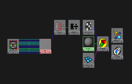
Below is a screenshot of the very simple network I am using and the zip file of the shader itself. The test render I got is identical to the previous expression method of offseting the values for the map so it looks promising.
setRangeExample.jpg

Please feel free to add to this network and post here if you like.

Attachments

networkHead.jpg

Interesting… i look forward to trying this out.
are yougoing to try some animation blending like the work Taron is doing, using messiah?

thanks for shareing! :smiley:

Yeah, something similar. I want to key displacements for specific wrinkle patterns and flesh folds off joint rotations, so I can control the level of multiple maps on a mesh based on what direction the arm or leg is rotating and by how much.
I hope it works.

hey Scott,

cool:+1: – did you come up with that yourself or did someone show you that? that’s the technique i use to demo when i taught at www.expression.edu :laughing:
the expression one is much easier to remember tho:D

I came up with it playing with the problem in the hypershade. I was vastly influenced by other members on this forum tho as well as the HyperReal Facial Rigging materials from Alias so I cannot claim sole authorship. Im trying to determine how to blend 2 maps now. I am using a plusMinusAverage node on the outputs of the set range node…
my render is cooking…
<<crosses fingers and waits>>

i was talking about the set range node thingy - was that in hyper real facial docs?

using a layered textured node might be another way to go on animating the textures. connect trans of each layer to blenshape weight.

good luck

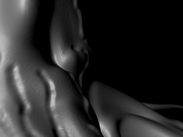
I’m using the grey scale map from Zbrush in maya mental ray, with the settings outlined in the tutorial and I’m getting stepped displacement.

for example, notice the lines. These were not painted in and in Zbrush it looks smooth.

[attach=13808]steps6do.jpg[/attach]

Attachments

steps6do.jpg

Check the filter you have on your file node. It may be set to Quadratic. Try turning this off. I also saw a similar artifact when I converted my maps to 16bit RGB using Fcheck instead of Photoshop… It may be an issue with the conversion. If the filter dosent help try reconverting in Photoshop making sure that color managment is off and you save it as an RGB tiff file.

Scott

so this was the displacement map that I exported from Zbrush that is doing this. I turned filtering off, but it’s still doing it. I converted the tiff to 16 bits in photoshop, with color management off, and I’m still getting this stepped pattern.

in my setting for Zbrush I had Adaptive and Mode turned on.

perhaps its important to note that my image is 1024 by 1024, should it be higher?