Ive been trying for the last week and change to figure out how to do this. Im pulling my hair out now. Ive seen all the threads from pixolator and such on it, read the user guide, but im still having 0 success. My model is coming out smooth with no kind of sculpting that resemles my zbrush mesh whatsoever, and ive been playing with a lot of the various settings and getting nowhere, ive exported 3 maps, positive,negative, and mid, played with alpha gain and alpha offset values in maya, and nothing is changing. Is there or will there be a simpler way of doing this god forsaken process? If i cant figure this out, then zbrush would be a total waste of money for me since I cant seem to use it for its intended purpose in my workflow. Please somebody help me out. Any and all help is appreciated. Thank you.
First, have you tried using the sample models and maps supplied for you here? If you cannot get those to come out right, then you know for certain that it is a problem with your settings in your rendering engine. If they turn out fine, but models that you create do not, then we’re looking at a workflow problem in ZBrush. In that case, we’ll need to know the exact steps that you’re following.
Also, have you read the tutorials in the FAQ? There is a section there on Maya.
ive tried the aborigine head, the sword, ive gone over the text in the in the user guide, i dont know. If you ask me, this process is made too hard and too much work in the first place. It should be WAY easier than it is, so somebody can focus on being more artisitc than being technical.
um…are you using the maya renderer, or mentalray? if you’re using mentalray, there seems to be a bug in the way maya exports subd’s and displacement to mr (the subd approx. overrides the displacement), so i currently use a polysmooth node instead of converting to subdivisions.
the alphaoffset is intended to push your image range back, so that it sits with 0 in the middle. so, for example, if you alphaGain is 1, then your alphaOffset would be -0.5, so that you image range straddles 0. i write an expression in the offset like this (if my file texture is called file1):
file1.alphaOffset=-file1.alphaGain/2
just replace file1 with whatever the texture node is called. also make sure that you’ve converted your image to either iff (which you can do via commandline using imgcvt or in fcheck) or rgb tiff (out of zbrush it’s a greyscale tiff), and that you’ve flipped the image vertically (you can do this in zbrush in the alpha menu).
Im using Mental ray for maya 6.01, and im also using the EXACT same settings that Scott Spencer from
<a href=“http://www.zbrushcentral.com/zbc/showthread.php?t=20310”>Aborigine head</a>
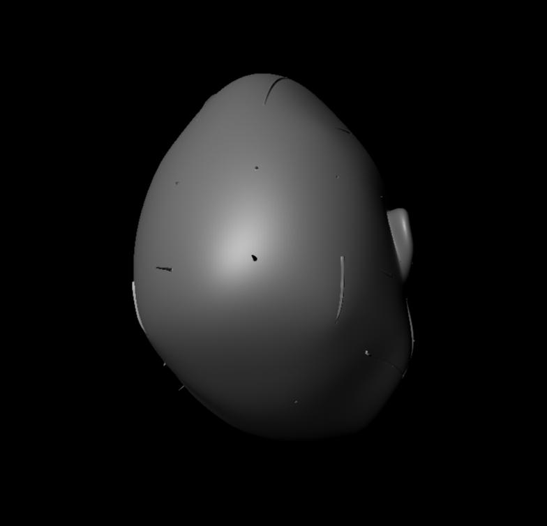
is using. Let me show you what im getting though when i render

Now i dont know whats going on to make it show different, but im gonna keep playing with it. Im also want to try your method sunit, but i dont know about writing an expression for alpha offset…where exactly am i supposed to i write this?, because i cant enter that in the alpha offset box, its looking for a regular number. Im gonna keep trying. Thanks
and how do i use a polysmooth node instead of converting to subdivisions?
i cannot figure this thin out.ive tried alot of tutorials with no success…can anyone help me out?
Hi, I have only had the pleasure of playing with the ple version but have found a huge amount of support in the learning process.
so I would ask have you checked out their forums for perhaps some info regarding this? Since it is more a maya related issue than a zbrush one at this point? Also did you check out the practical guide…I thought there was a tute for zb to maya in there but of course can’t testify to any accuracy there in but perhaps you will find the missing link you are looking for?
Hey fanmap529,
I have experimentd a lot since that last post so here is a breakdown of what you need to do
In photoshop make absolutely sure that color managment is turned off it is under Edit>Color Otherwise when you open your maps to flip them or converty to RGB it will shift your gay values causing the displacments to “bloat” wven if the rest of the render settings are correct.
Open the map in photoshop, flip vertical and convert to RGM. Make sure your color managment was turned off before you open the map.
Save this map and open Maya.
in maya create a displacement material ( I use Lambert but it is a matter of preference). Load your converted map in the file node and set the alpha gain to 12 and your alpha offset to -6 or what is preferable an expression. In maya you can enter expressions into any feild you can type as long as you start with the = sign so in the alpha offset type
= -file1.alphaGain /2;
the file1.alphaGain refers to the node file1 which should be the name of the file node attached to your displacement shader. Not to complicate matters but if you see no displacement at all make sure that your file node in the hypershade is indeed file1 and not file2 or file3.
that way you can just change alpha gain and the offset will update accordingly.
In the attribute editor on your shape node make sure “featuee displacement” is turned off. This disables Maya’s settings so they dont interfere with Mental Ray’s approximation editors which are, essentially doing the same thing but better.
now with your mesh selected go to the Approcimation editor. Here is where things can get tricky expecially if you dont happen to be a Mental Ray guru (which I am most certianly not). In Mental ray subdivision at render time is called approcimation where in other renderers it is called tesselation. The subdivision apprioximation editor subdivides the entire mesh based on the settings you supply whereas the displacement approximation editor selectively subdivides based on what is required by the map. The two can work in tandem very well except for high frequency details which will seem a little more subtle in MR than in Z but in a lot of cases this is because the lighting in Z the shader which has specularity and other factors including cameras. You can smooth the model instead of using the subdiv approximation but frankly it dosent really make for the best looking surface as it can result in strange edges and faceting.
I add a subdivision approximation and a displacement approximation to the mesh. Keep the default settings for now just make sure both are set to Spatial and fine view high quality. make sure view dependent is off for both editors.
Now do a render.
You should start to see displacements coming across immidately. Now if the model isnt smooth enoughor you are getting the gross forms but not enough details try increading the subdiv approximation editor to 4 min 6 max with .01 length.
the length tells the renderer how small the largest triangle edge can be when it subdivides. Thhe smaller this is the longer the render will take and the better it will look.
I set length to at the very most .1 on displacement usually .01 in subdiv I will often go to .001 for really fine details.
I bounce back and forth here between the subdiv and the displacement approximation editors gently increasing the settings until it looks good. You should not need a bump map at all in mental ray all that detail is in your displacement map and should come across with the proper settings. The editor that have the most effect on the qualoty of the displacemetn and the details is the subdivision approximation. The model will only displace as much as the geometry supports. So if it subdivides to little the render wont be able to suppor tthe details you want.
try this out. I am not at school at the moment so I dont have my scene file with me where I rendered this model. I will upload a copy of it for you to look at later today. And I will post the specific numbers I used for each setting.
For you own models keep this in mind SCALE MATTERS!!! Notice that when you import the Pixolator head it is huge compared to the maya grid at the defaut settings. It actually measures a couple feet in Maya space but if your own models areonly a gfew inches across Mental ray seems to care about this and will require far smaller settings in the alpha gain and not look nearly as nice. Mental Ray also figures scale into it’s lighting model so consider that as well.
I hope this helps somewhat. Please feel free to post back with any more questions concerning rendering these maps.
Scott Spencer
PS a neat thing to help troubloeshoot is to go into the render globals and under translation in the mental ray tab set messages to progress. This way you can see (in the maya output window) how high the mesh was subdivided. If this number is far below the poly count of your highest subdivision level in Z then you need more subdivision.
very, very informative Scott, I shall try everything you’ve just said and get back to you to let you know my progress. Thanks
One more thing, how many different displacement maps do I really need? i see tutorials saying (one mid, one negative, one postive), some saying 2(saying mid, negative), and some saying just 1. All these variances I just dont know, so really, how much?
Just generate one. Set the res to 4096 Adaptive mode and turn off smooth UV.
Glad it helped, let us know hjow it turns out.
Scott
Ok here are some screenshots that may help out. Note that I went ahead and addded a smooth node on the head. You may also notice “banding” in the textures. To fix this set the filter type on the file node to Gaussian.
Lemme know if you need anything else.
Ciao!
Scott


thank you ever so much mr Scott Spencer, i finally got a render like the rest of you guys. Im glad i can stop pulling my hair out now 
Now to get started on my real projects which were put on hold due to this problem. Once again, thanks to Scott and everybody else for the help. Bye for now
one thing, do you ever have to play around with the texture palette at all when generating the displacement map from zbrush?
As a general rule, no you dont. All your displacement map needs are fufilled by the alpha menu. There are occasions when you would use the texture menu to help generate masks or diffuse maps but those are specialized and unnessacary to creating the displacement map itself
Scott
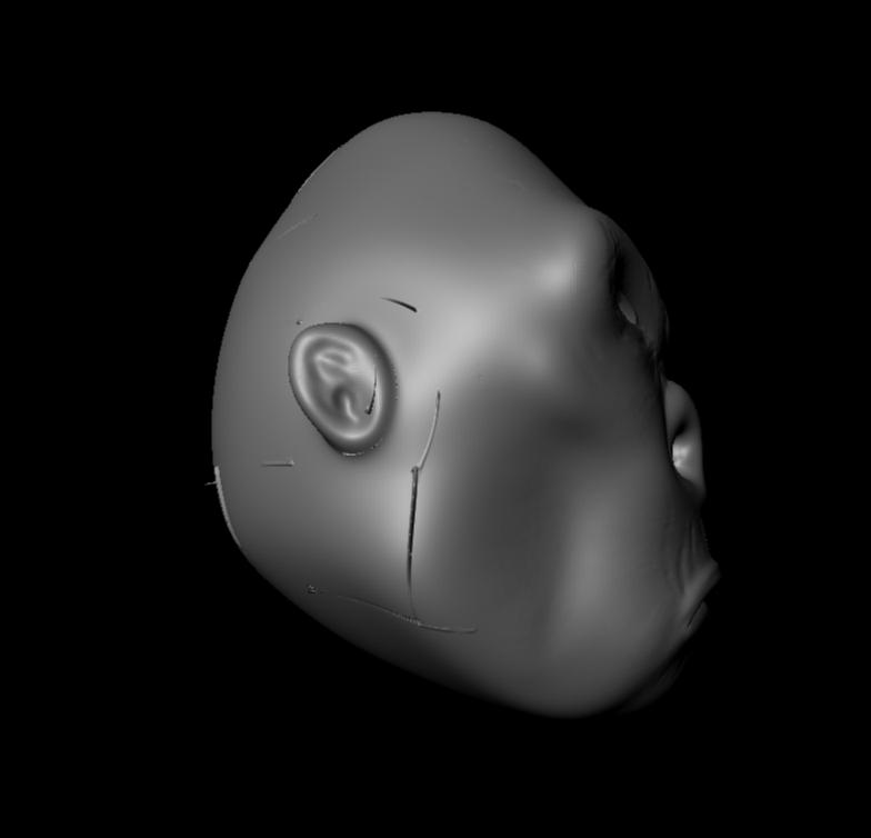
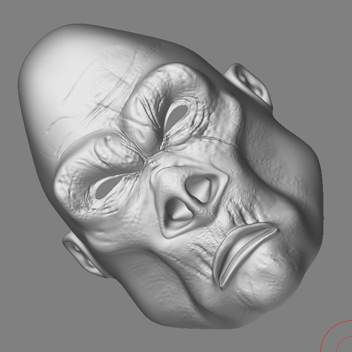
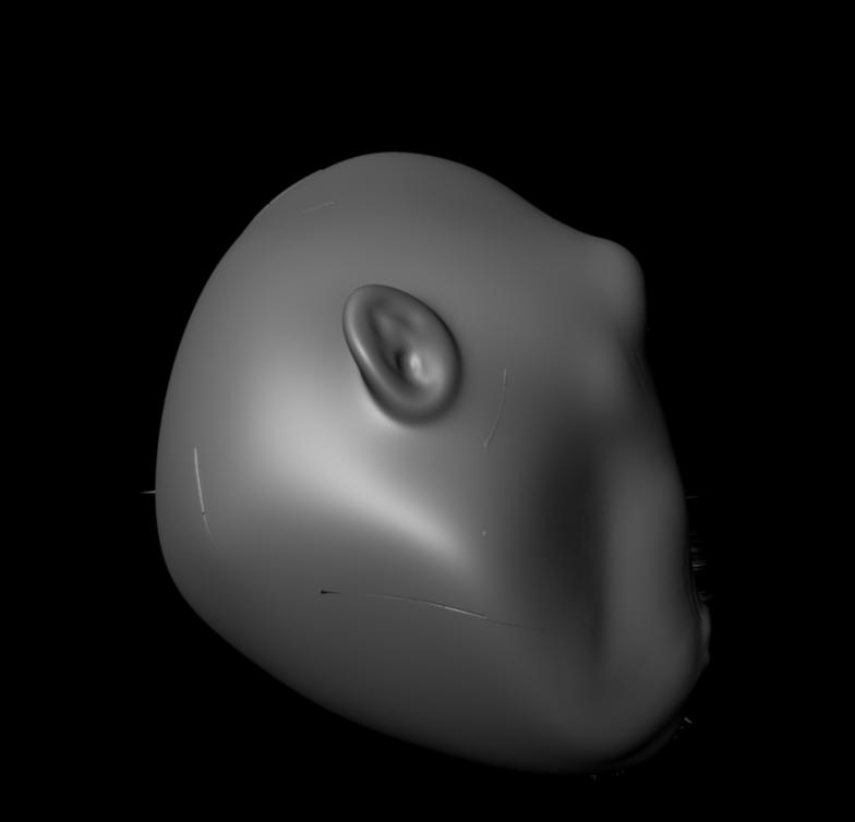
Ok, this is what im seeing now, and i dont quite understand whats going on. I dont know whats casuing these mesh artifacts, when they are nowhere present on my zbrush mesh… here is the zbrush version:

Anybody know whats going on?
Attachments


I have seen these before and I have yet to determine exactly what causes them. Hopefully someone can chime in with specifics. I hve fixed these problems before by one or more of the following approaches:
recreate dispalcement map with smooth UV on
Make sure you exported a 16bit TIFF from Z then convert to RGB in PS. I doont export PSD from Z
Increase your subdivision approximation settings
Check the UV texture ediotor and makle sure that none of these artifacts are falling on the UV borders on the model, if so you may have a problem with the smooth node causein issues with the UVs Alias has a new tutorial on their site on how to fix this.
Any other ideas anyone? I have a spike like this on my elephant I cant determine what is causing it.
Scott
Also make sure that your texture rendering settings have MIP mapping or texture antialiasing turned off.
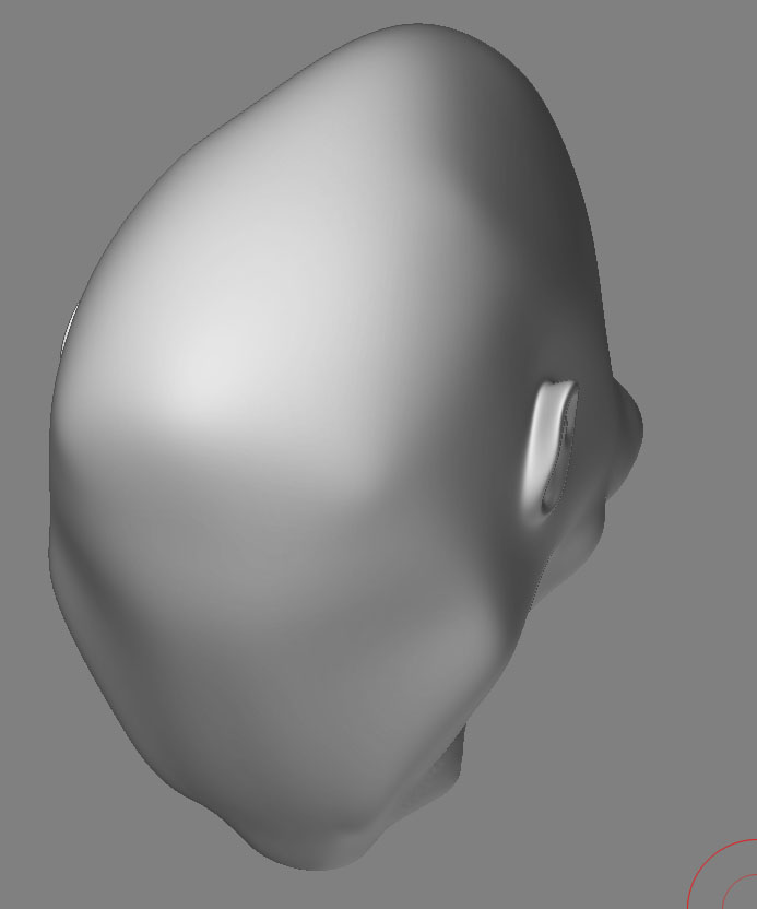
this is the latest with ur latest suggestions scott, im starting to loase all hope and might soon give up
Attachments
